EFHW Build
NOTE: if any parts in your kit are lost, missing, or damaged for any reason, please email me and I’ll be happy to help get you back on track with what you need.
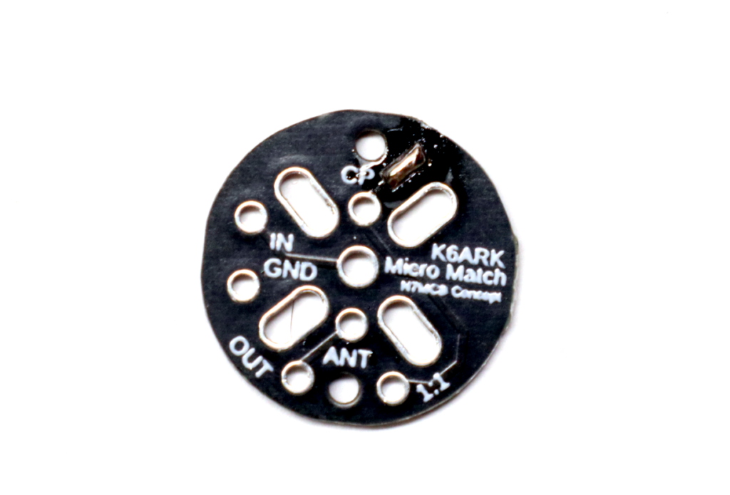
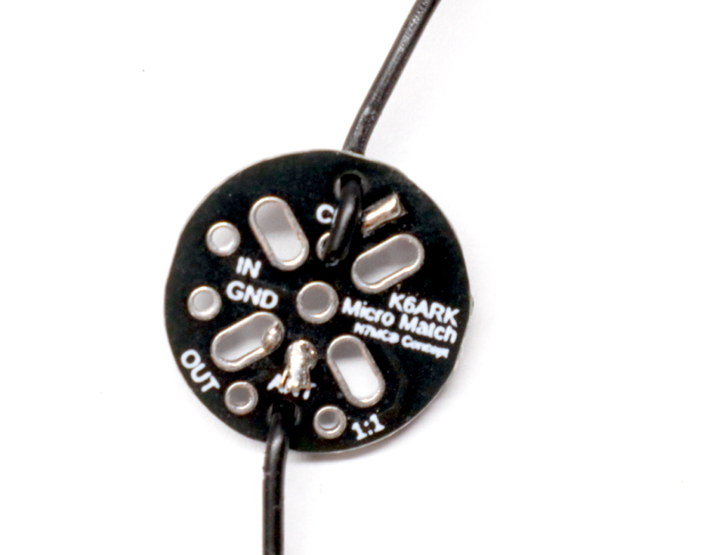
Step 1: (Optional) Solder the Counterpoise Jumper.
If you plan to build your antenna with a counterpoise (optional), join the “CP” pads on the top of the board with a small blob of solder.
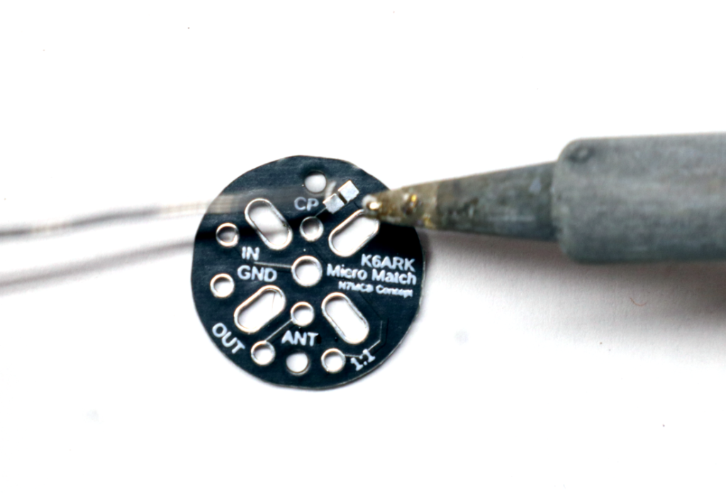
Inspect closely to confirm the solder has bridged across the gap between the pads.
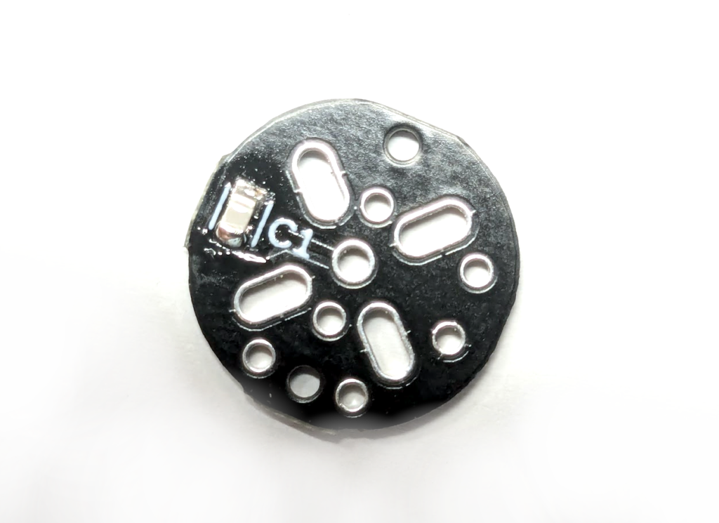
Step 2: Install the capacitor.
Find the small capacitor and carefully remove it from the package. Find the “C1 pads on the bottom side of the board.
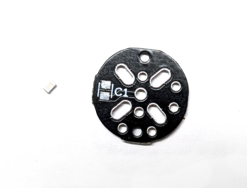
Place a small amount of solder on one SMT solder pad on the board.

Use tweezers to position the capacitor onto the pad while melting the solder blob with the soldering iron.
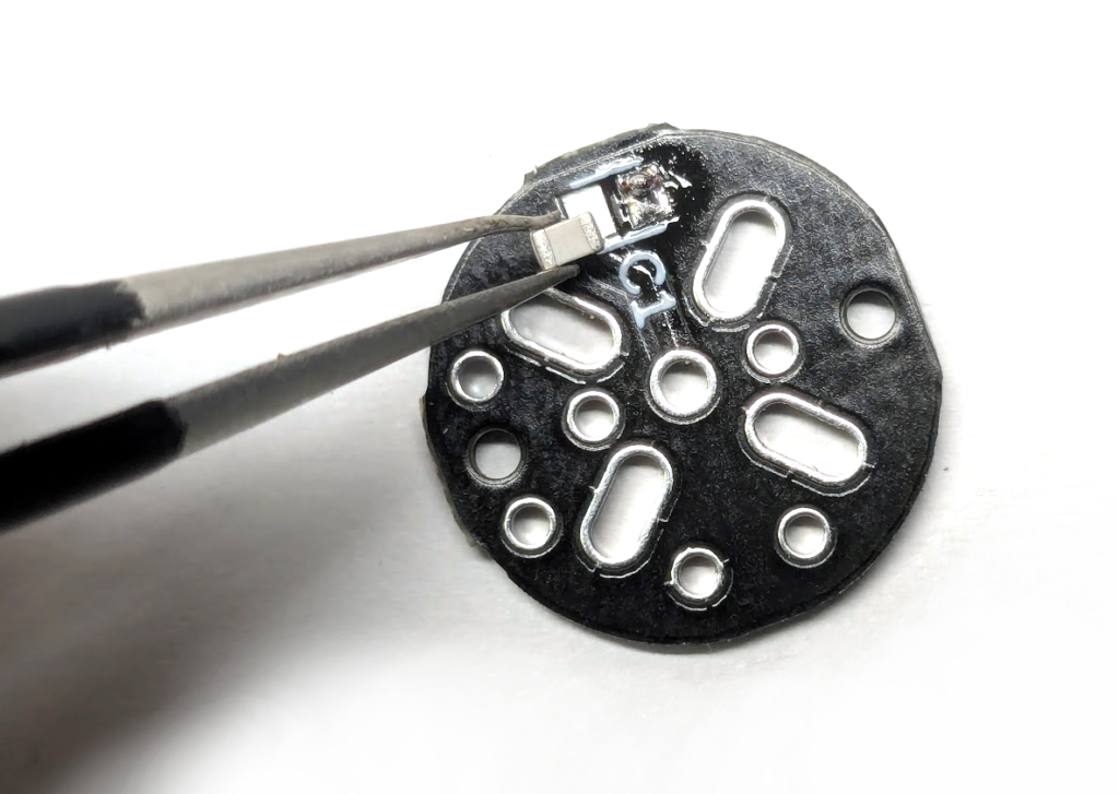
With the capacitor soldered into place and secured at one end, solder the other end of the capacitor to the board.
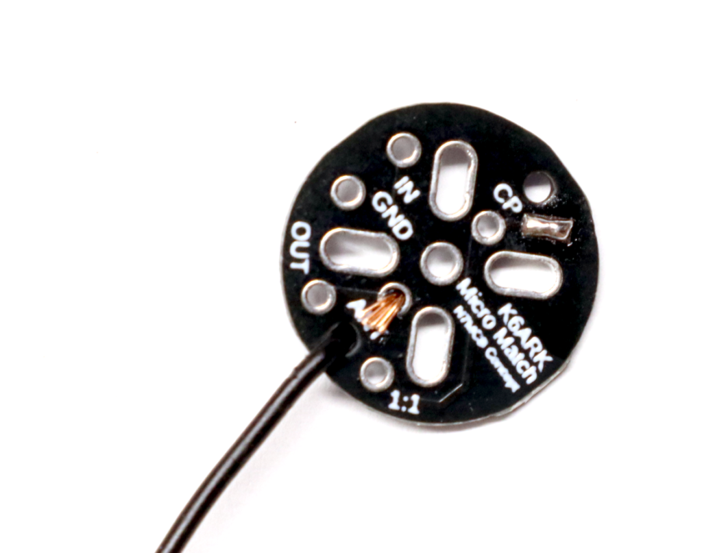
Step 3: Install the Antenna Wire Stub.
Cut the Poly Stealth wire in half.
Strip about ⅛” of insulation from the end of the wire and insert the stripped end through the strain relief hole on the top of the board, and then the stripped end into the ANT pad.
Solder the wire to the pad.
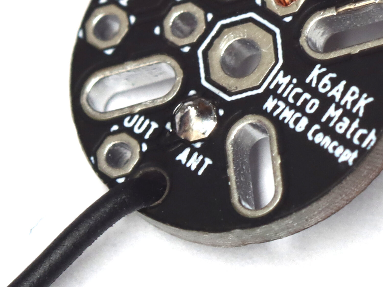
Step 4 (Optional): Install the Counterpoise Wire.
Take the remaining Poly Stealth wire and strip about ⅛” of insulation from one end.
Insert the stripped end through the strain relief hole on the bottom (capacitor side) of the board, and then the stripped end into the CP pad from the top of the board as shown. Solder into place.
Note: The orientation is the opposite of the ANT wire.
Note: The supplied stub of wire is 26 ga Poly Stealth and the insulation melt at soldering temperatures. If you are concerned about shorts, place a small piece of the small heat shrink on the wire between the strain relief hole and the solder pad.
Step 5: Wind the ~49:1 unun toroidal transformer.
Note: For the 20w kit, nest the two toroids concentrically, and then follow these instructions treating the two toroids as if they are one. All other instructions are the same.
Uncoil the magnet wire. Begin winding the magnet wire as shown below, making three turns through the toroid.
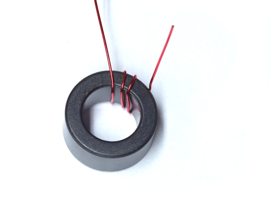
After three turns, make a wire stub about an inch long by forming a small loop and gently twisting it.
Caution: Twisting the stub wires too tight may break the magnet wire.
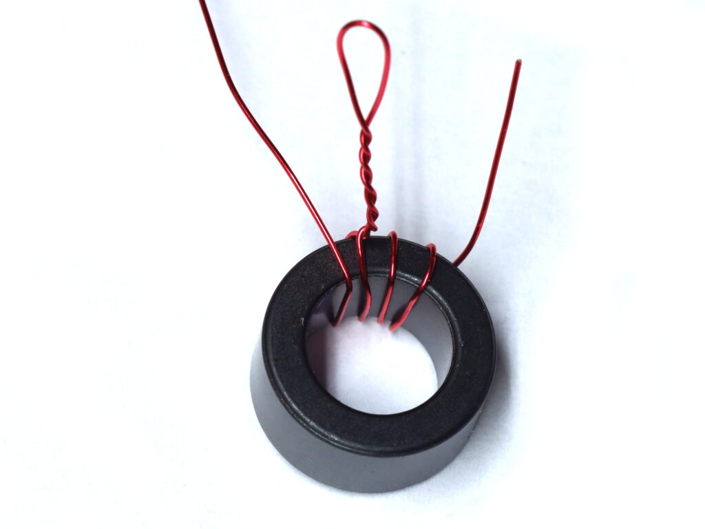
Continue winding the wire in the same direction around the toroid for a total of 19-24 more turns. 20 turns seems to provide an optimal match for general use and is the recommended build.
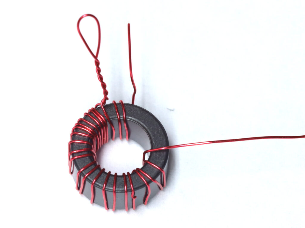
Note: Each time the wire passes through the center of the toroid counts as one turn. I have found that 3 primary (IN) and 21 secondary (OUT) turns works well for this kit for 40m. For optimization on 80m, use 24 secondary turns, and for optimization on 20m and up, use 19 total secondary (OUT) turns.
Step 5: Prepare wire stubs for soldering.
Trim the wire stubs to about 1″ . Strip enamel from each stub using a razor blade or knife to scrape it off and expose bare copper.
Alternatively, if you use a hot soldering iron (350-400C), you can burn off the magnet wire in the next step. Simply hold the iron on the soldered pad until the enamel burns off and solder flows throughout the joint.
Step 5: Solder the toroid to the PCB.
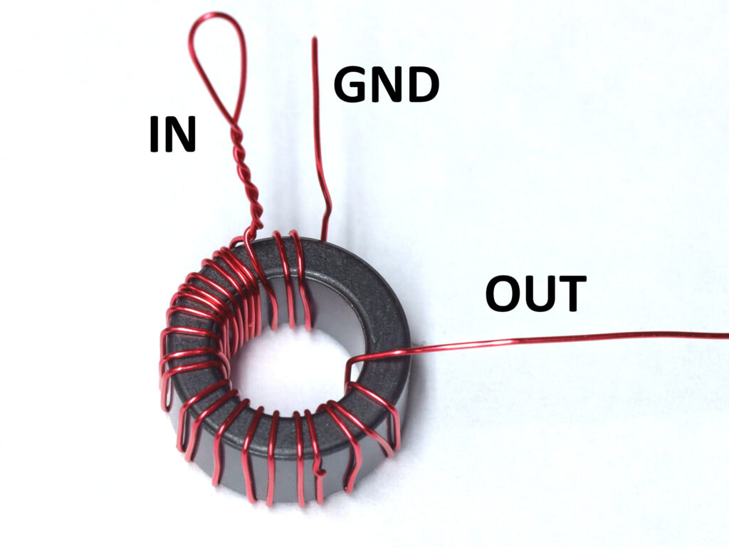
Insert the wire stubs into the appropriate PCB holes – the stub exiting the middle of the toroid where you started your windings goes to “GND”, the twisted pair to “IN”, and the end of 19-24 winding secondary coil to “OUT.”
Note: Capacitor not shown in photo but should be installed on your board.
Solder into place, and trim the stubs.
Hold the hot soldering iron on each solder pad for 5-10 seconds to burn off any remaining enamel and ensure a good solder joint.
Step 6: Test.
Inspect your solder joints. Ensure no solder bridges exist.
Test for cold solder joints with a DC multi-meter. You should find continuity (close to 0 ohms resistance) between the BNC center pin solder pad, BNC ground solder pad slots, and the antenna wire. If you find an open circuit or high resistance, reheat each magnet wire solder pad for 5-10 seconds to allow solder to burn off the enamel and flow into the joint.
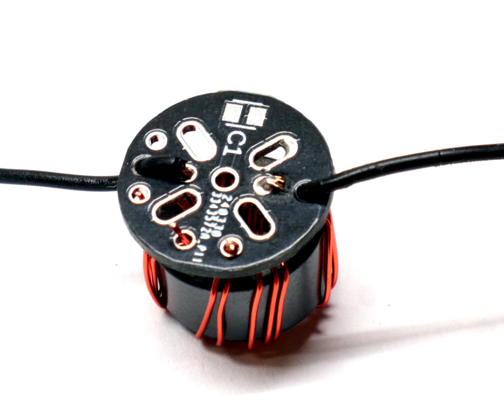
Step 7: Solder the PCB assembly to the BNC connector.
Kits packed after Sept-2025 include a PCB spacer. Install it on the BNC connector between the main PCB and the connector.

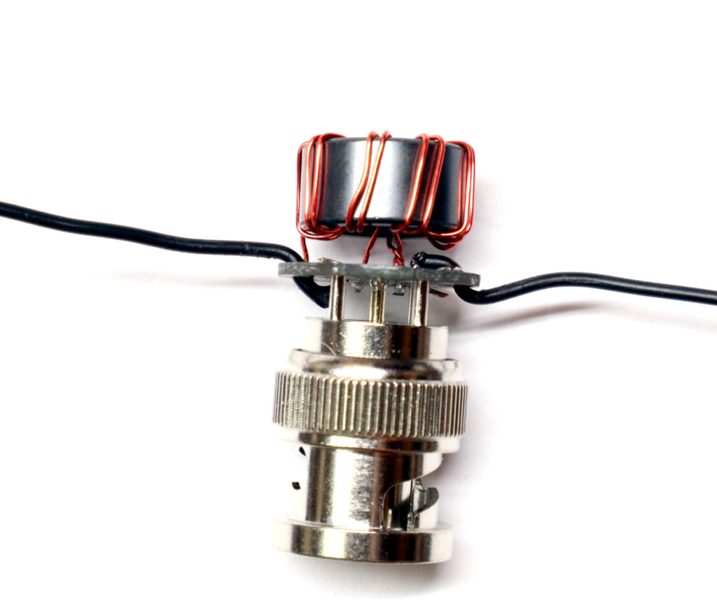
Gently flex the toroid up away from the board. Install the assembly onto the BNC connector, pressing it on far enough for the top of the BNC pins are flush with the top of the PCB.
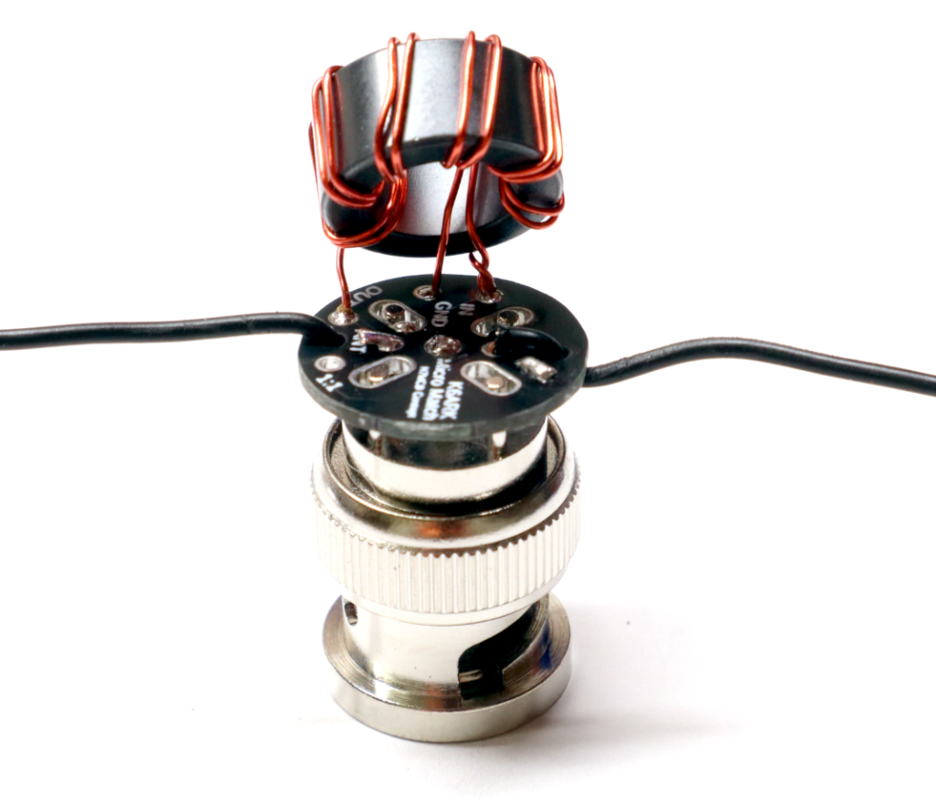
Start by soldering the center pin and adjusting the position of the board. DO NOT press it down flush to the BNC connector or it will short out.
Once you are happy with the position, solder as many of the outer pins as possible. Two pins are plenty strong, but solder as many as you like.
Note: The ground pins on the BNC connector benefit from solder flux to get the solder to properly flow. Use it if you’ve got it.
Step 8: Test the matching unit.
Kits packed after Sept 2025 include two resistors. The tan one is a 2k ohm resistor, and the blue one is a 453 ohm resistor. Connect them in series to make a 2453 ohm resistor.

Attach a 2453 ohm resistor between the antenna wire and ground, and test using a SWR meter. SWR should be under 3:1 across the HF bands and near 1:1 for many.
Alternatively, set up a half-wavelength wire outside and connect the matching unit with an antenna analyzer. You should see a dip to under 1.5:1 SWR at the resonant frequency of the wire.
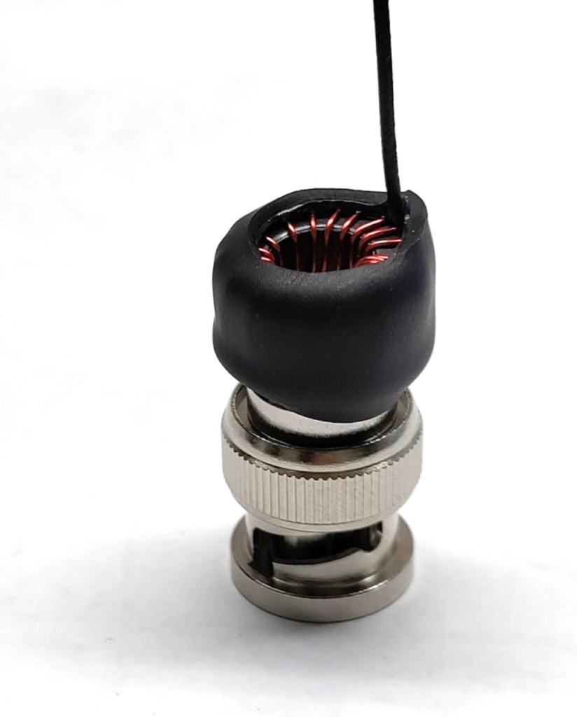
Step 9: Install heat shrink.
Cut the small heat shrink roughly in half. Install the longer heat shrink onto the “ANT” wire stub, and the shorter piece of heat shrink onto the “C-POISE” stub if used. Slide them down against the PCB and shrink into place. This heat shrink can help with fatigue resistance for durability.
Trim the section of the 3/4″ dia heat shrink section (1” dia for the 20w kits) 1/4″ longer than the height from base of PCB to top of toroid. Place the heat shrink over the toroid and PCB, and shrink into place. This provides protection for the PCB and toroid.
Now your matching unit is built, let’s turn it into an antenna.
Step 10: Attach and tune the radiating wire element.
For a mono-band EFHW, measure and cut slightly more than ½ wavelength of wire, then fold back or trim to resonance.
Adding a small loading coil of about 12 turns on a .7” plastic former placed 6 feet from the feed point will help make a 40m half-wave resonant wire also be resonant on 20m and 15m. Build and tune this coil before trimming the wire. I typically tune the antenna initially with the remaining spool of wire still attached to the end, unfurling what I need.
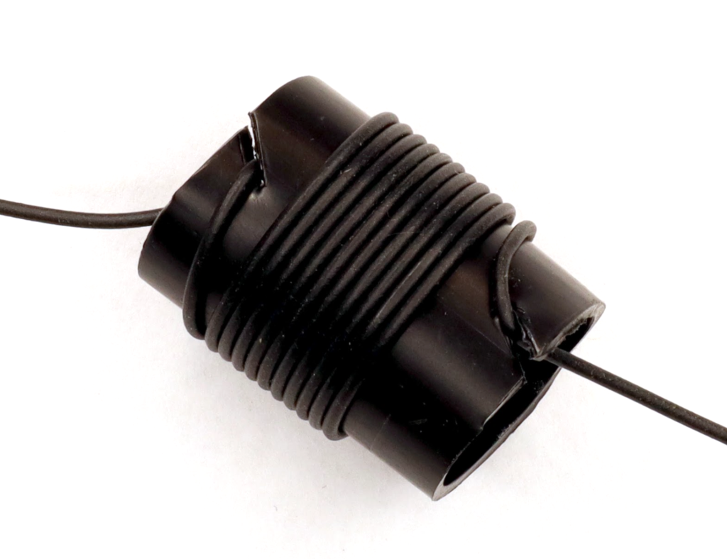
Drill or poke a small hole (preferred) in the plastic tubing to feed the wire through to secure the ends of the coil, or cut slots as shown above. Cover with tape, to secure it temporarily, then use the second piece of larger heat shrink in the kit to permanently secure the wire onto the coil. Tune the remaining wire length to resonance on 40m and check resonance on the harmonics, 20m, 15m, and 10m.