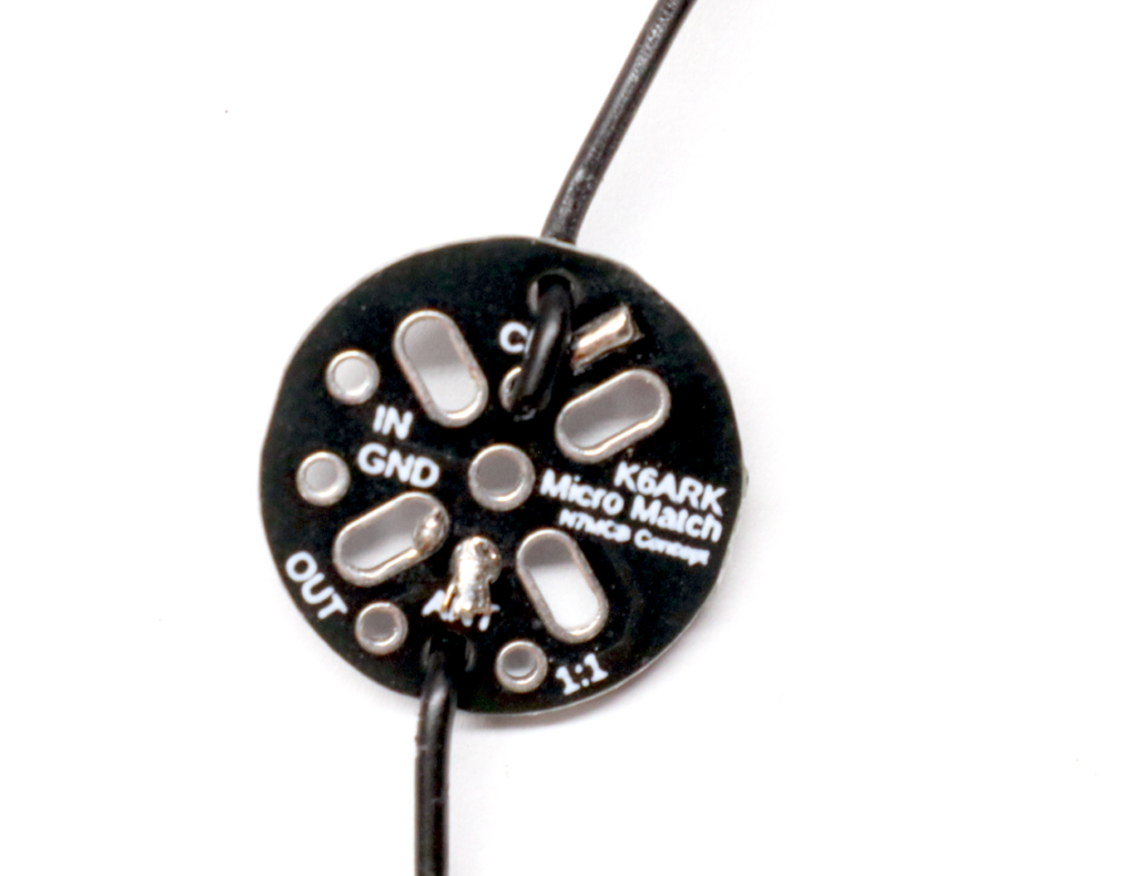
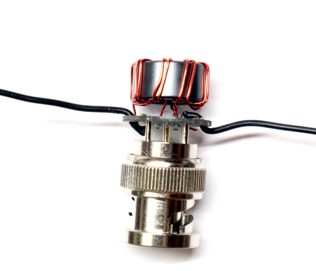
Step 1: Solder the Counterpoise Jumper.
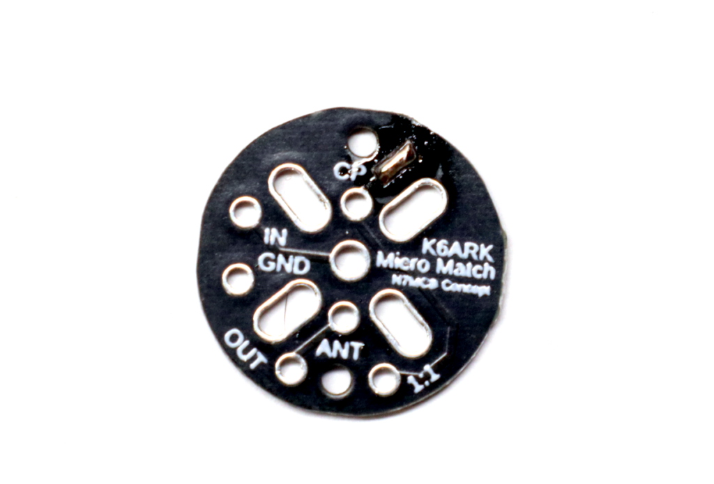
Join the “CP” pads on the top of the board with a small blob of solder.
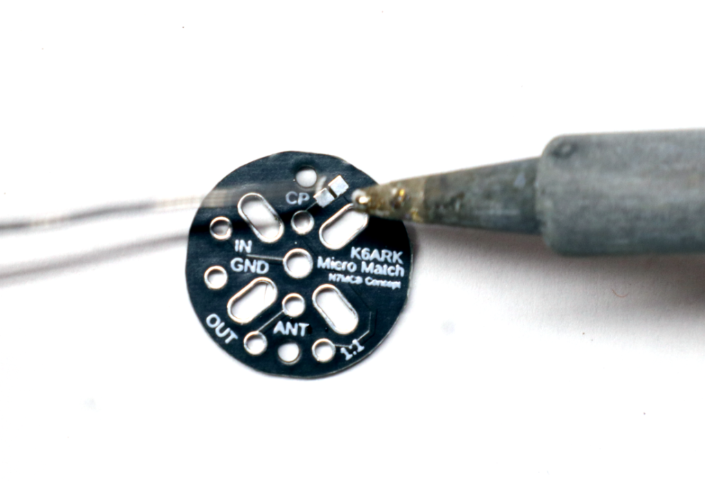
Inspect closely to confirm the solder has bridged across the gap between the pads.
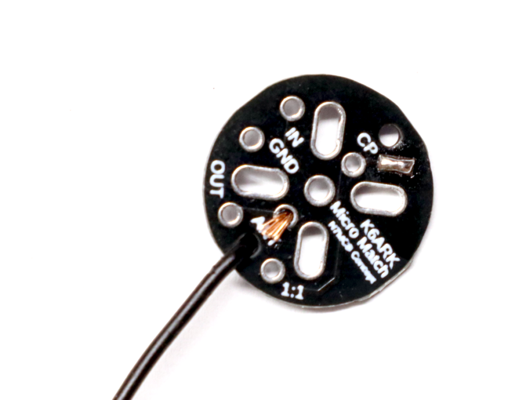
Step 2: Install the Antenna Wire Stub.
Cut the Poly Stealth wire in half.
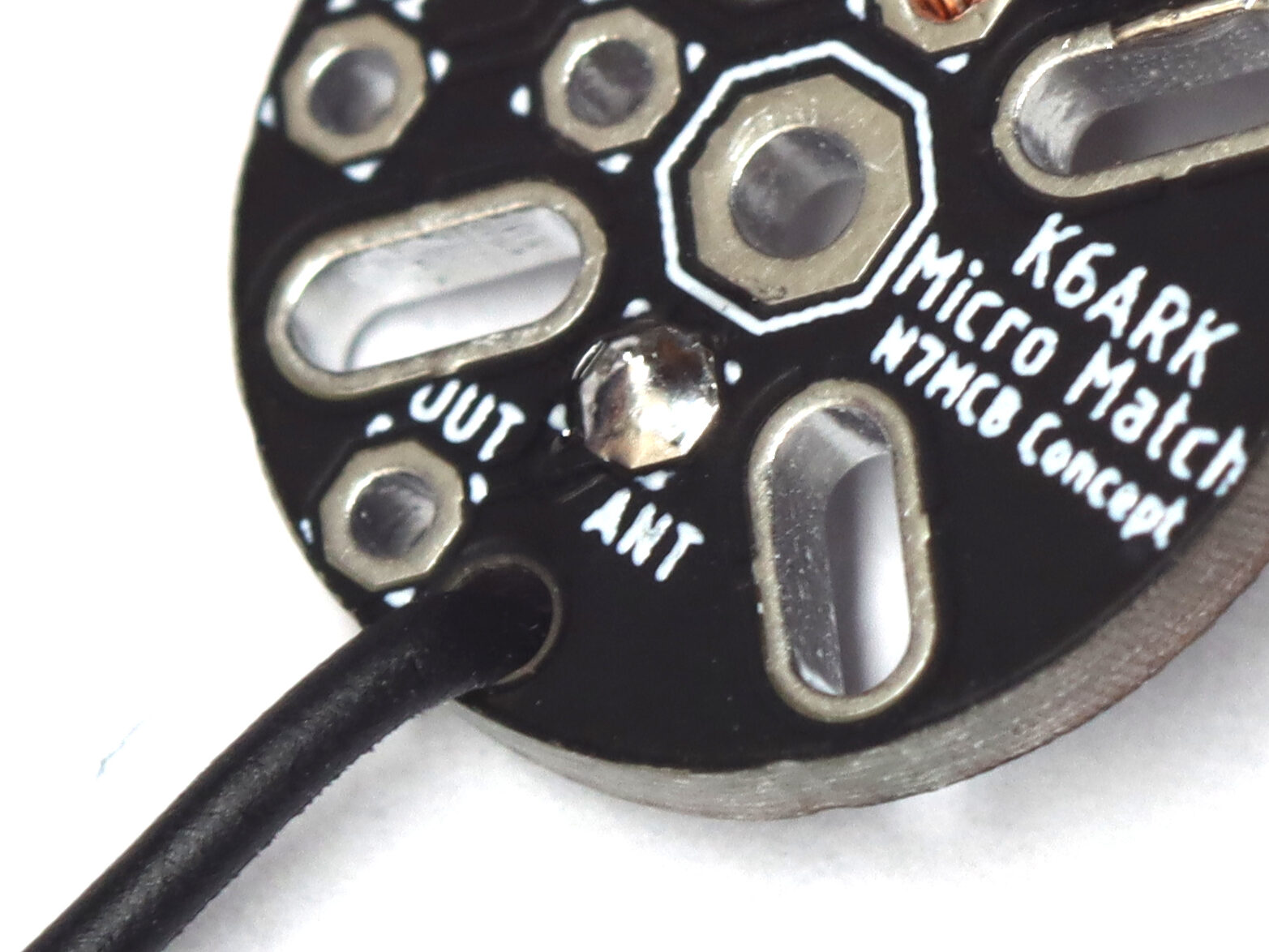
Strip about ⅛” of insulation from the end of the wire and insert the stripped end through the strain relief hole on the top of the board, and then the stripped end into the ANT pad.
Solder the wire to the pad.
Step 3: Install the Counterpoise Wire.
Take the remaining Poly Stealth wire and strip about ⅛” of insulation from one end.
Insert the stripped end through the strain relief hole on the bottom (capacitor side) of the board, and then the stripped end into the CP pad from the top of the board as shown. Solder into place
Note: The orientation is the opposite of the ANT wire.
Note: The supplied stub of wire is 26 ga Poly Stealth and the insulation melt at soldering temperatures. If you are concerned about shorts, place a small piece of the small heat shrink on the wire between the strain relief hole and the solder pad. Step 1: Install radiating wire and counterpoise stubs.
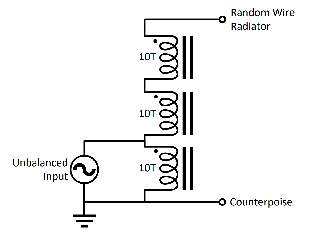
Step 4: Wind the 9:1 unun toroidal transformer.
Note: For the 20w kit, nest the two toroids concentrically, and then follow these instructions treating the two toroids as if they are one. All other instructions are the same.
Uncoil the magnet wire. Start with the end of the wire in the center of the toroid and begin winding as shown in the image to the right. Make about 7 full turns, evenly spaced around the toroid. The starting end of the wire will solder to the “GND” pad on the PCB.
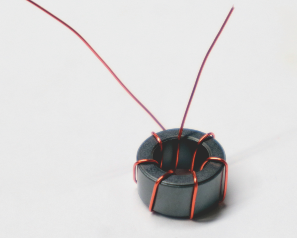
As you reach the position of the end of the wire, make a small stub by twisting the wire as shown below.

This will connect to the “IN” pad on the PCB. Continue winding 7 more turns around the toroid.
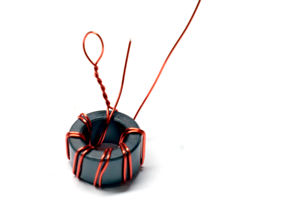
Continue winding the remaining wire around the toroid next to the previous turns another 7 turns. Finish just before reaching the twisted pair. This wire stub will connect to the “OUT” pad.

Step 5: Prepare wire stubs for soldering.
Trim the wire stubs to about 1″ long. Strip enamel from each stub using a razor blade. Remaining enamel will burn off when soldering if the iron is 350 C or hotter.
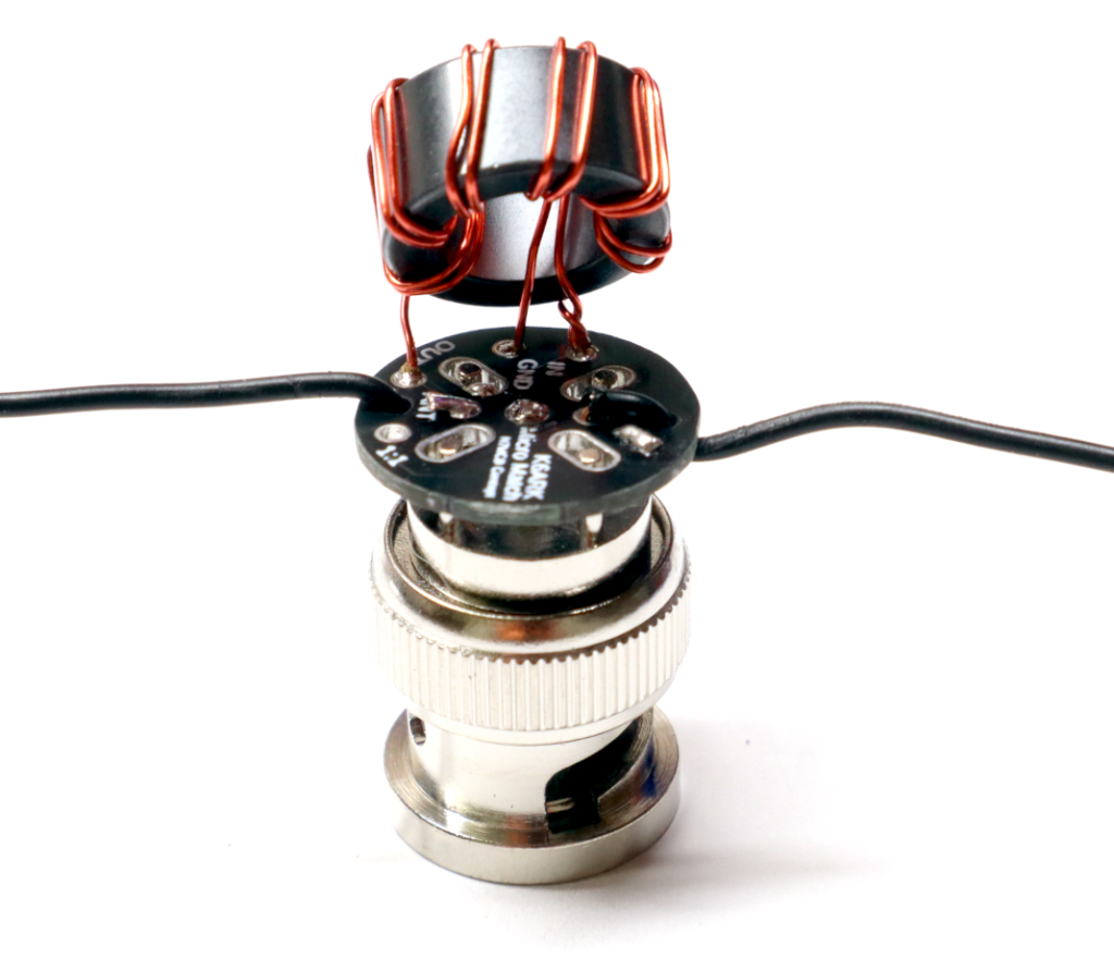
Step 4: Solder the toroid to the PCB.
Insert the wire stubs into the appropriate PCB holes – twisted pair to “IN,” end of longer winding secondary (2 laps around the toroid) to “OUT”, shorter winding primary (1 lap around the toroid) stub to “GND.” Solder into place, and trim stubs.
Step 5: Test.
Inspect your solder joints. Ensure no solder bridges exist.
Test for cold solder joints with a DC multi-meter. You should find continuity (close to 0 ohms resistance) between the BNC center pin solder pad, BNC ground solder pad slots, and the antenna wire. If you find an open circuit or high resistance, reheat each magnet wire solder pad for 5-10 seconds to allow solder to burn off the enamel and flow into the joint.
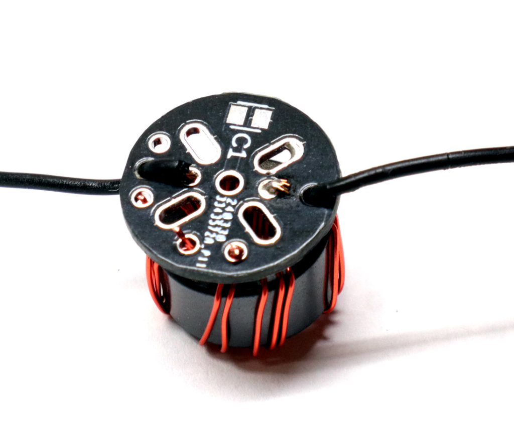
Step 7: Solder the PCB assembly to the BNC connector.
Gently flex the toroid up away from the board. Install the assembly onto the BNC connector, pressing it on far enough for the top of the BNC pins are flush with the top of the PCB.
Start by soldering the center pin and adjusting the position of the board. DO NOT press it down flush to the BNC connector or it will short out.
Once you are happy with the position, solder as many of the outer pins as possible. Two pins are plenty strong, but solder as many as you like.
Note: The ground pins on the BNC connector benefit from solder flux to get the solder to properly flow. Use it if you’ve got it. .
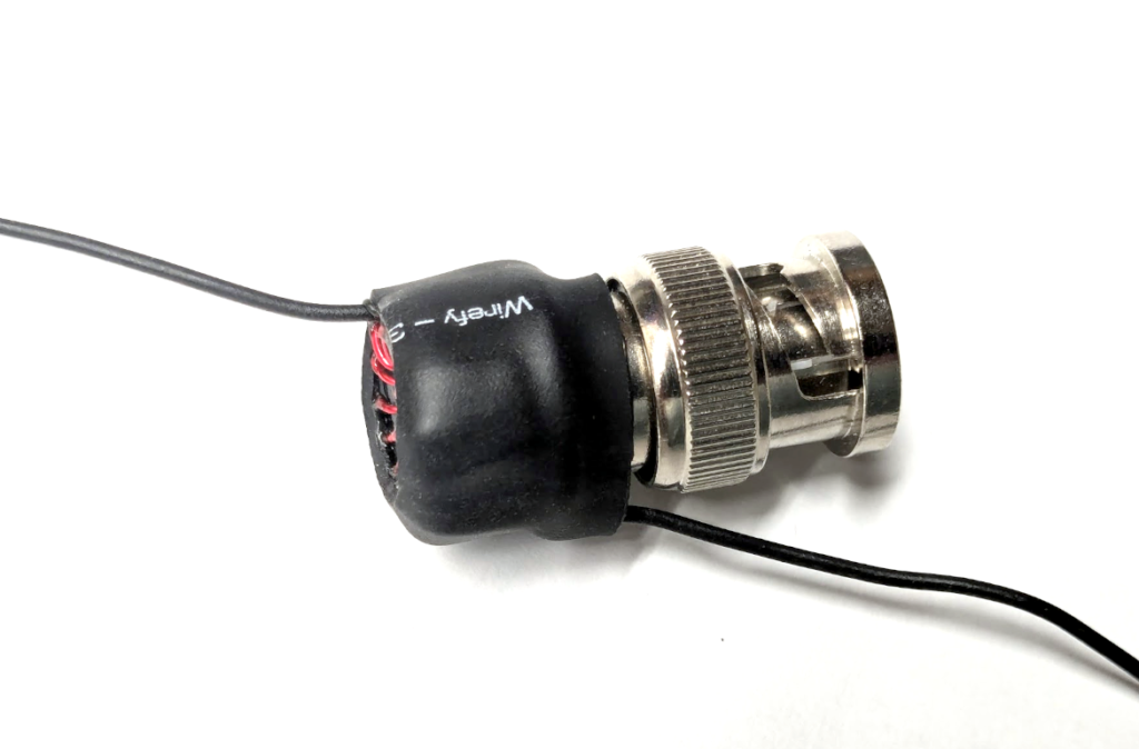
Step 8: Install heat shrink.
Place the 3/4″ heat shrink section (1” dia for the 20w kits) onto toroid and PCB as shown, with the ANT wire exiting the top of the matching unit, and the CPOISE wire exiting toward the BNC connector. Shrink into place with a heat gun. This provides protection for the PCB and toroid.
Step 7: Attach wire elements.
Attach a 17 ft counterpoise to the shorter wire stub (C-POISE). Attach a “random” length wire to the longer wire stub (ANT) – I recommend 41 ft which should be usable on 10m through 80m with a KX2, KX3, T-1 tuner, or Xiegu X5105.