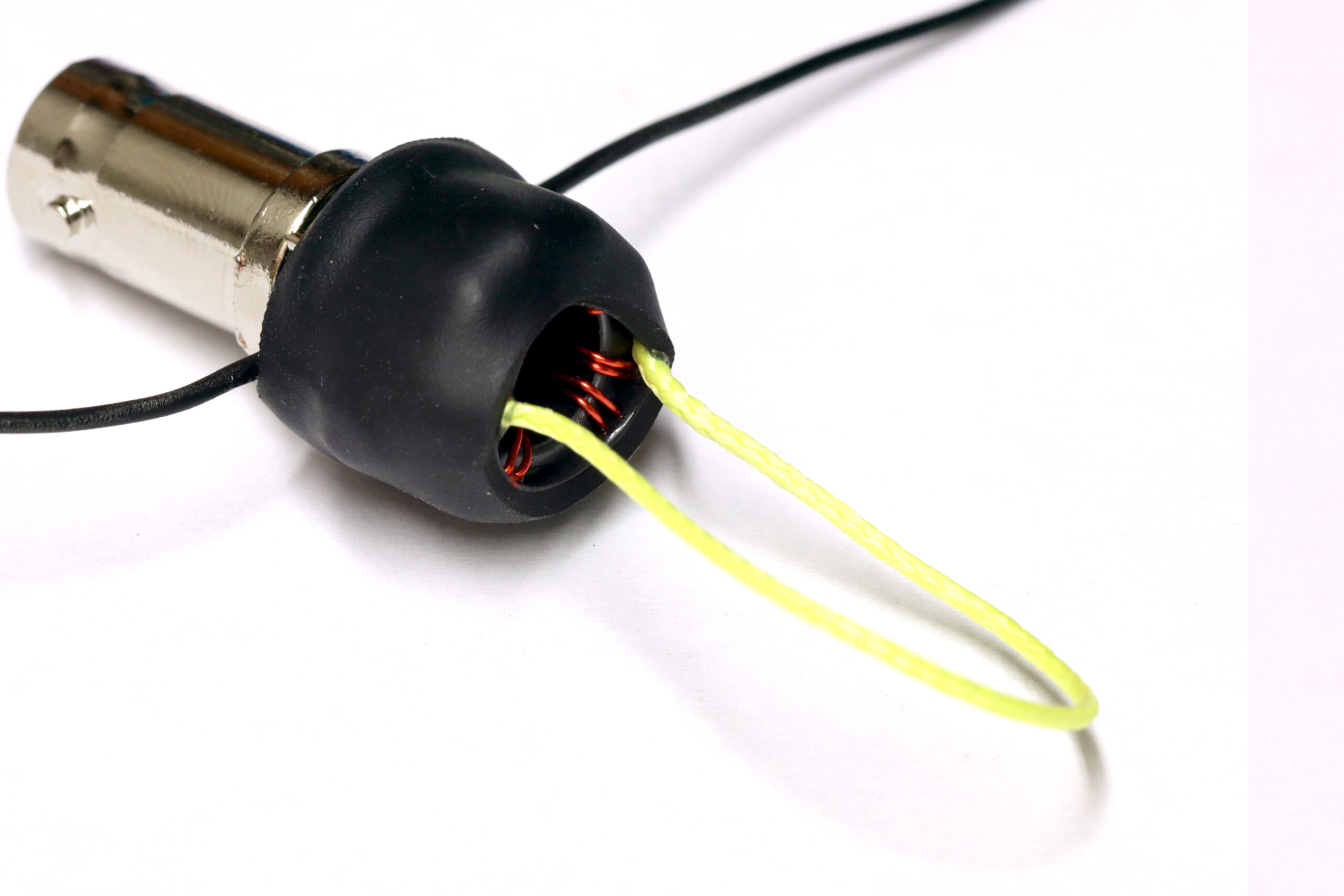
Even the “QRP” kit will handle 50+ watts when used as a 1:1 balun. It makes a great dipole center. Here’s how to build it.
1.) Attach Wire Stubs
Cut the length of poly stealth wire in half and strip about 1/8″ of insulation from one end of each piece. Insert into the PCB as shown.
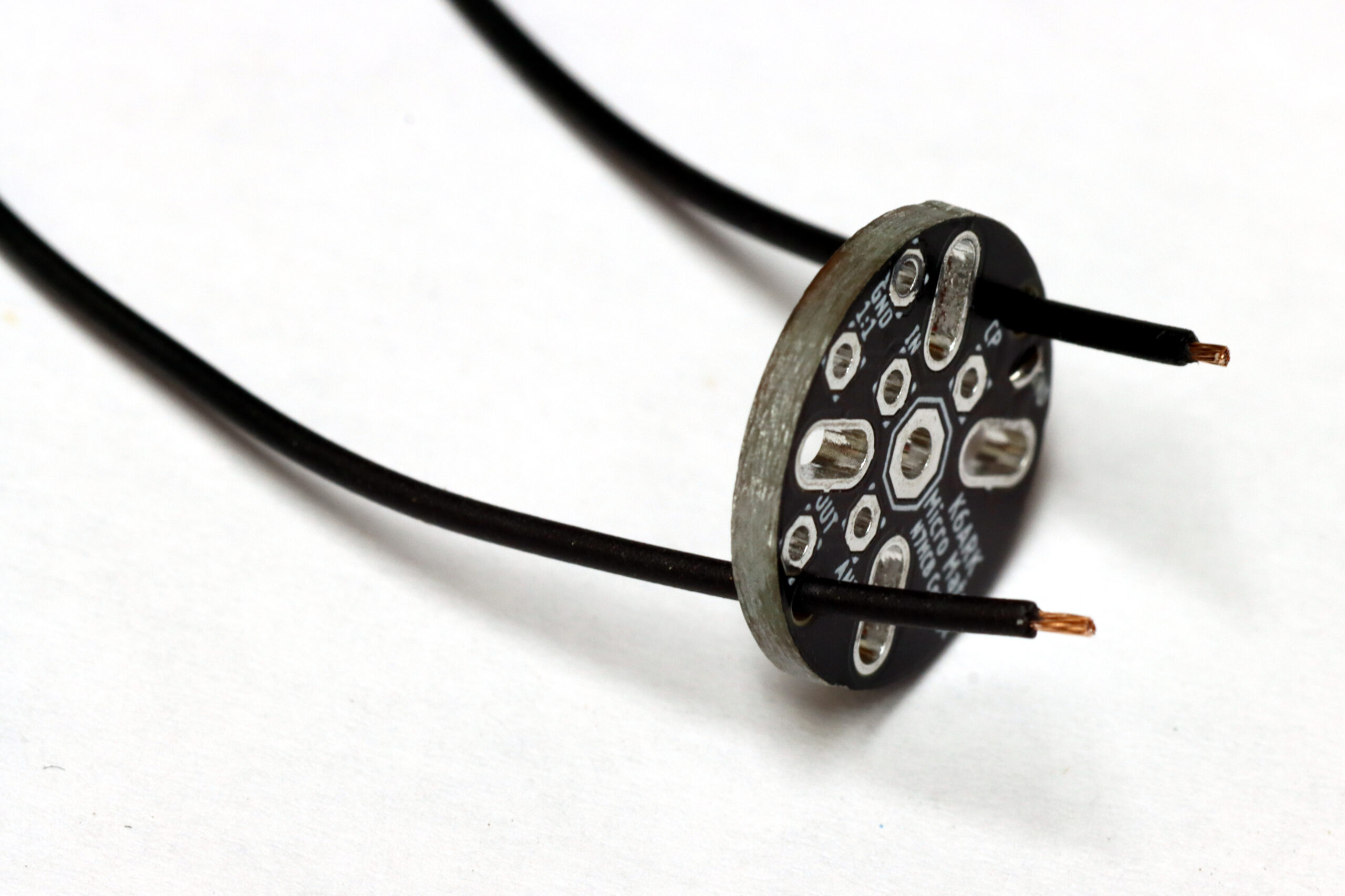
Insert the stripped wire ends into the corresponding pads.
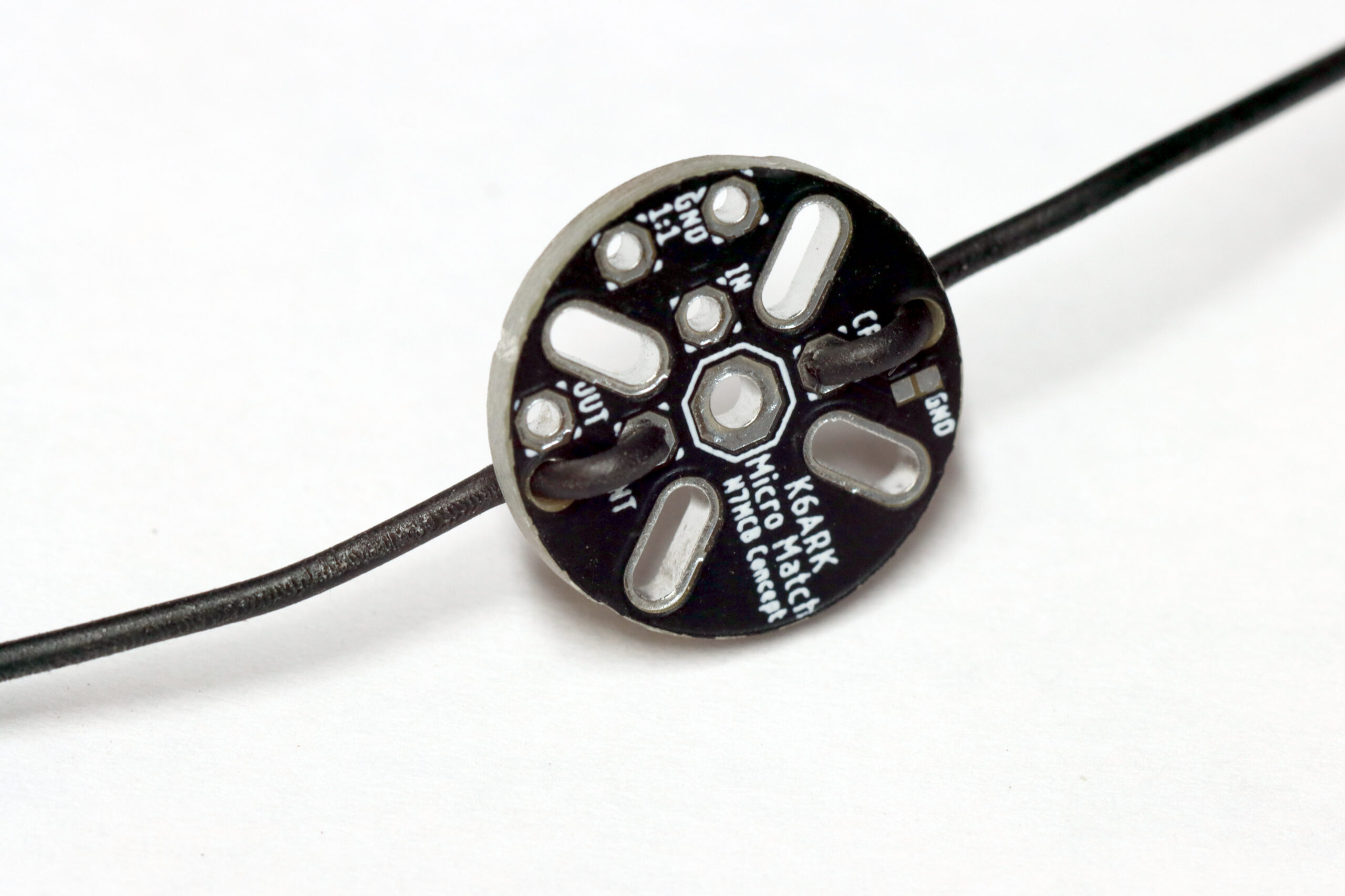
Solder into place.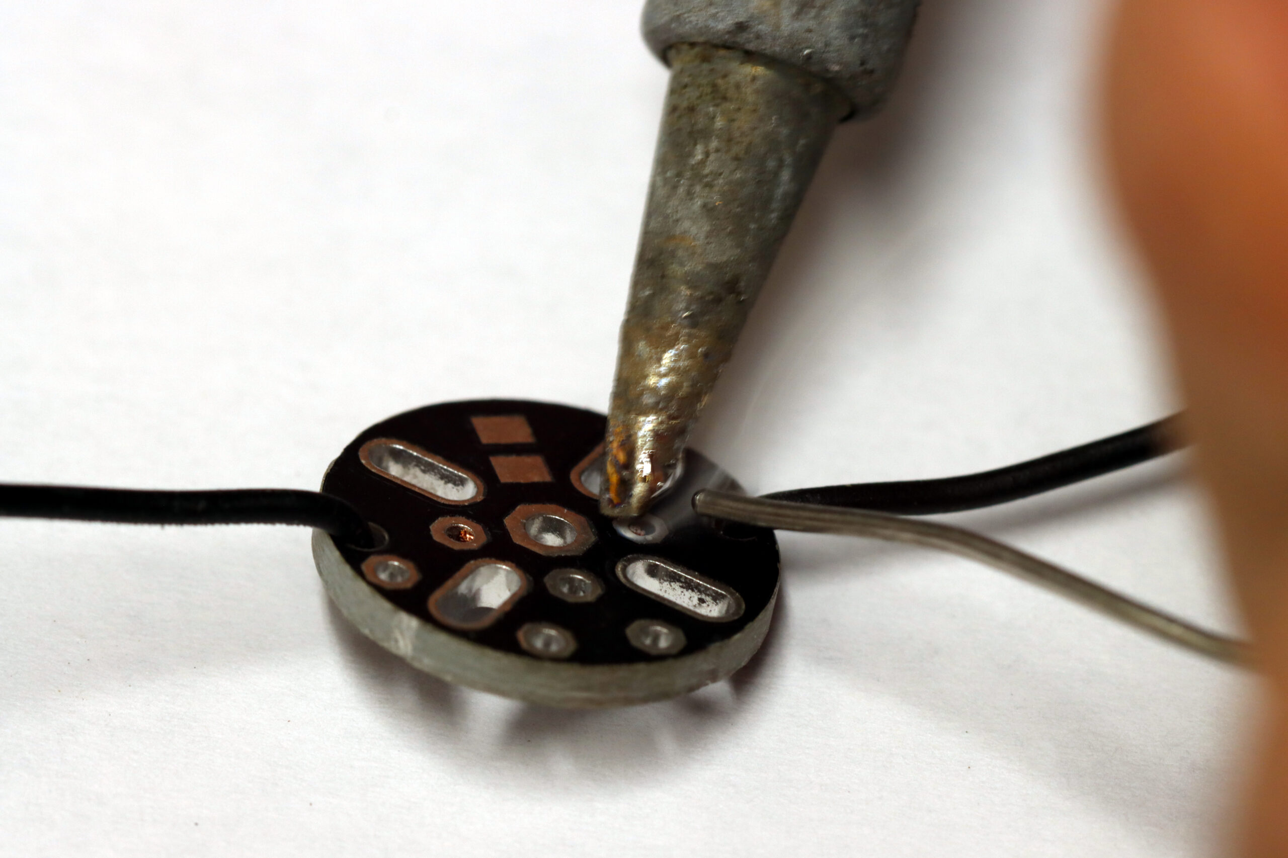
2.) Wind the Toroid
Note: For the 20w kit, nest the two toroids concentrically, and then follow these instructions treating the two toroids as if they are one. All other instructions are the same.
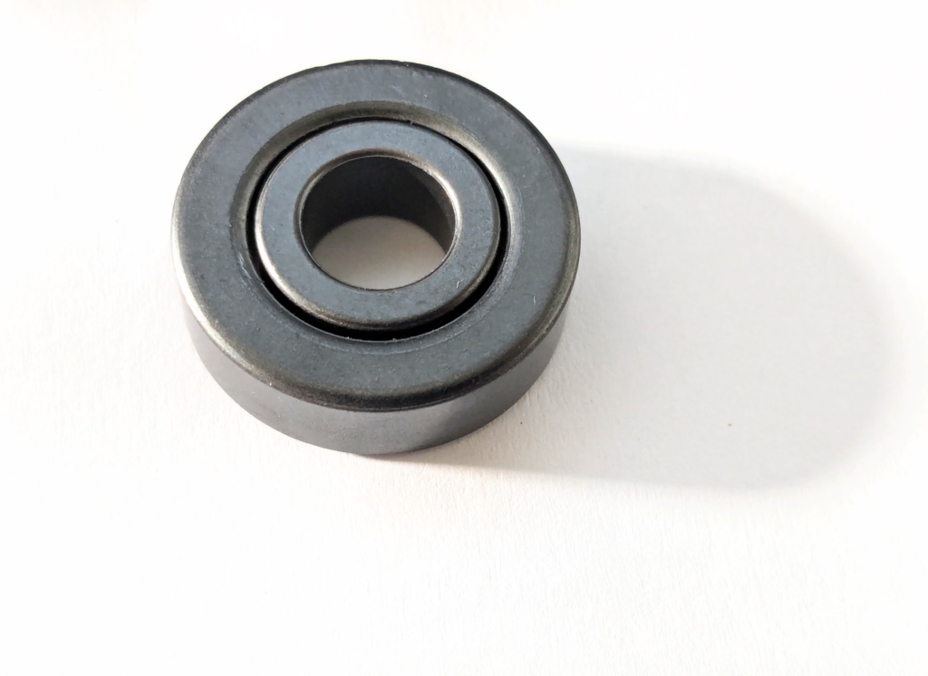
Uncoil the magnet wire and fold it in half. Start winding the two wires together around the toroid as shown.
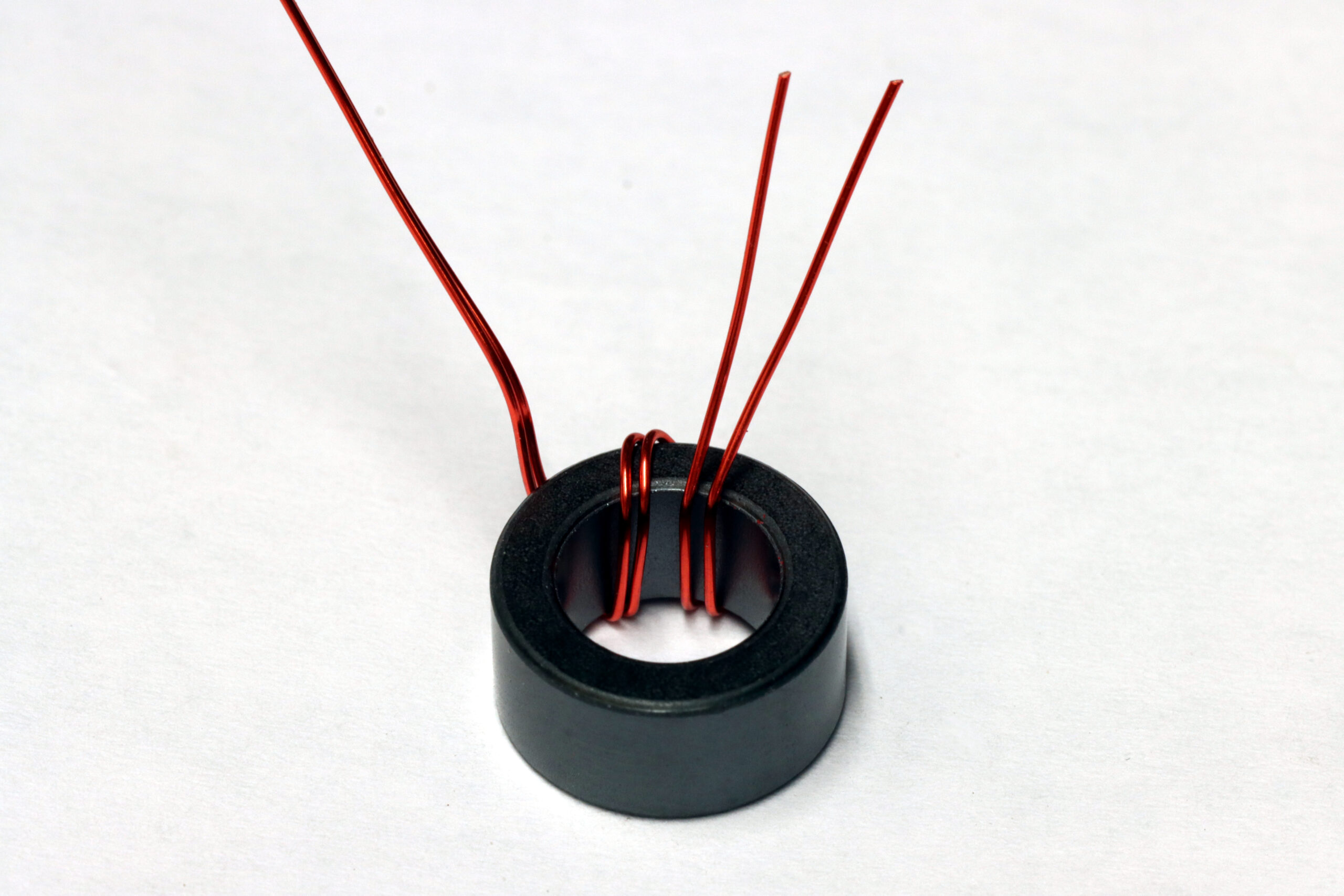
Continue the bi-filar winding for 10-12 turns around the toroid. It is ok if the wires cross, but keeping them parallel is good for style points.
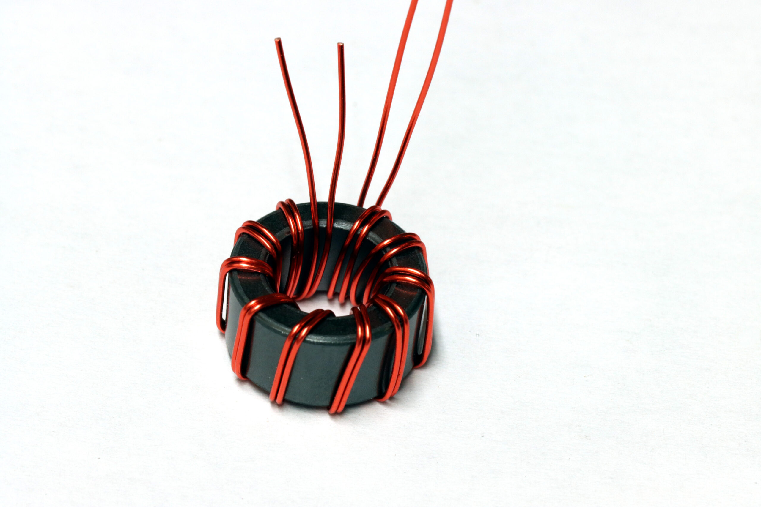
Trim the folded wire ends to about an inch long after you’re done winding.
3.) Attach the Toroid to the PCB
Strip enamel from the wire stubs if you don’t have a very hot soldering iron. If your iron gets up to 400 C / 750 F, you should be able to simply burn the enamel off of the wire with hot solder.
Insert the wire stubs into the toroid as shown. One end of the windings connect to the “IN” and “GND” pads, and the other ends connect to the “OUT” and “1:1” pads. It does not matter which of the input wires connects to which output for a balanced antenna.
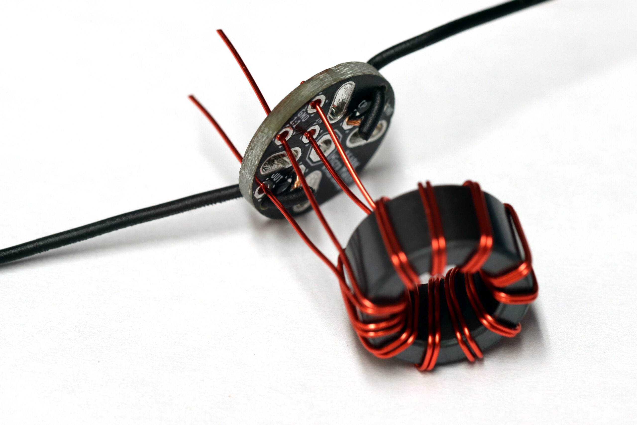
Position the toroid near the board and solder into place and trim the wires. Hold the soldering iron on the pad for 5-10 seconds until the enamel burns off and solder flows throughout the joint.
4.) Attach the PCB to the BNC
Position the PCB flush with the tips of the connector and solder the center pin.

Reposition as necessary while heating the solder, then solder at least two of the ground lugs to the PCB. Flux helps. It takes a good amount of heat to get the solder to flow onto them (they are big heat-sinks).
5.) Install Hang Cord (optional)
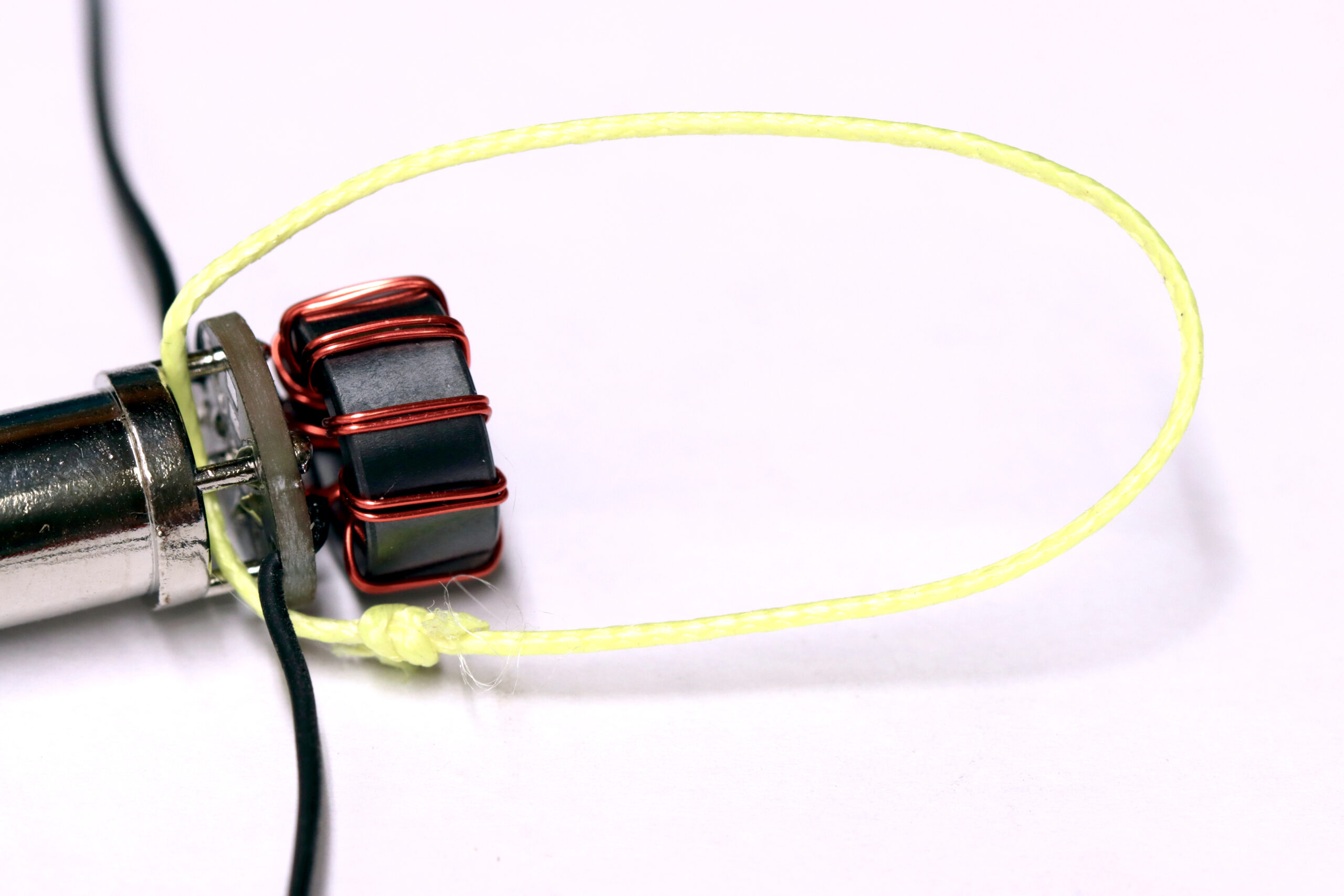
Tie a short piece of cord (not included) to create a hang-point for the antenna.
6.) Install Heat Shrink Tubing
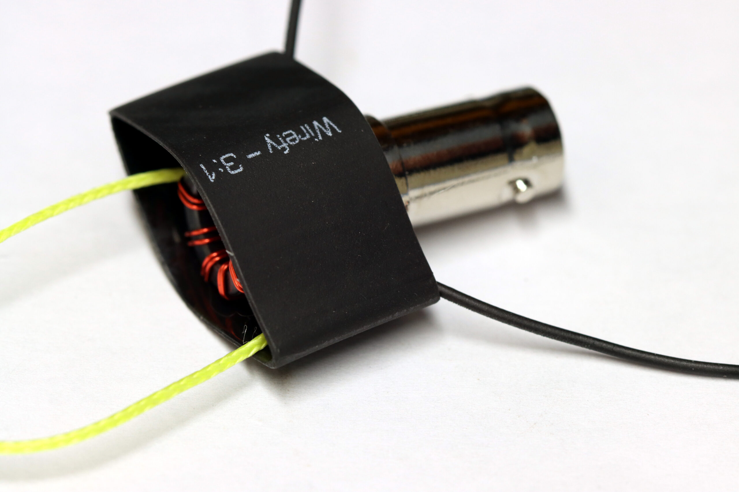
Place the 3/4″ (QRP) or 1″ (20w) heat shrink tubing over the matching unit and shrink into place.
Add some wire, and get on the air!
