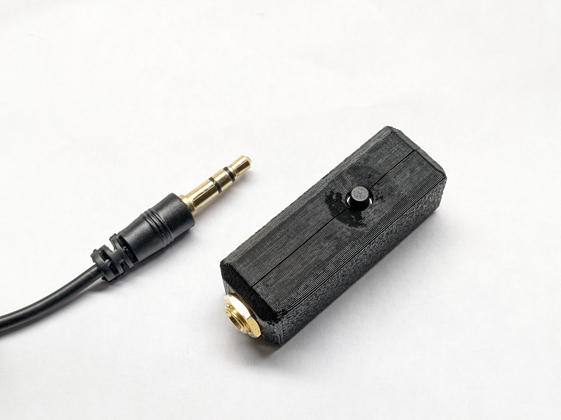
If you want to print your own, download the files from www.printables.com.
BILL OF MATERIALS:
Links are Amazon Affiliate links – It costs you nothing more, but I get a few cents on the dollar from Amazon if you purchase through these links.
| Mandatory Items | Qty | Source |
| 3d Printed Top | 1 | Print from STL (PETG preferred) https://amzn.to/3H9QN4p |
| 3d Printed Bottom | 1 | Print from STL (PETG preferred) https://amzn.to/3H9QN4p |
| 3.5 mm TRS Panel Mount Jack | 1 | https://www.digikey.com/en/products/detail/schurter-inc/4832-2300/1731055 ($2.73 ea) https://amzn.to/3Hadrd2 (10 pack $7.99) |
| 6 mm x 6 mm x 7 mm Push Button Switch | 1 | https://www.digikey.com/en/products/detail/cit-relay-and-switch/CT11027-0F100/16607792 ($0.15 ea) https://amzn.to/3Wt1jIy (100 pack $6.99) |
| QMX 9.7mm Electret Condenser Microphone Element (-24db) | 1 | https://www.digikey.com/en/products/detail/pui-audio-inc/AOM-5024L-HD-F-R/12152286 |
| TruSDX, FX-4CR, and Elecraft 9.7 mm x 6.7mm Electret Condenser Mic Element | 1 | https://www.digikey.com/en/products/detail/cui-devices/CMA-6542TF-K/1869979 ($0.80 ea) https://amzn.to/3CbkQph (10 pack $5.99) |
| 26-32 ga hookup wire | 200 mm | https://amzn.to/3G2bqi2 (198 ft 30 AWG $9.99) |
| Additional/Optional | ||
| Aux Cable (4 ft) | 1 | https://amzn.to/3XZ1IUo |
Build Instructions
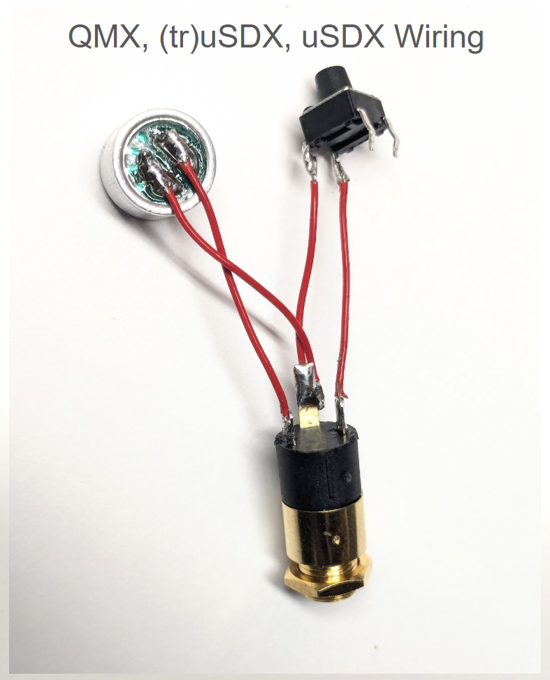
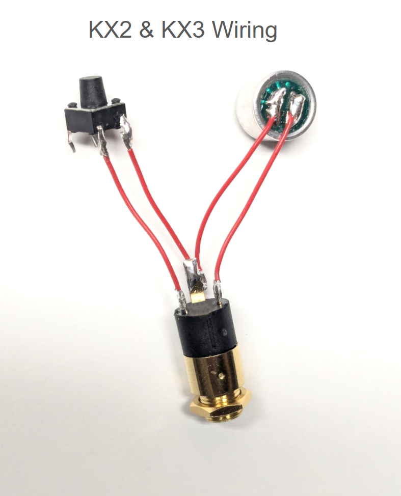
1.) Cut wire and solder mic and switch to jack.
Cut four pieces of wire to 1.25 in / 30 mm in length and strip 1/8 in / 3 mm of insulation from each end. Solder wires as shown in images below.
Look closely to find the “ground” traces on mic element that connect the ground pad to the microphone element case. Be sure to connect the ground pad to the ground lug (the long one) on the 3.5mm jack.
ATTENTION: Use the images below to identify proper wiring for the KX2/KX3 vs. the QMX/(tr)uSDX. I believe the ZBitX uses the Elecraft wiring. If you build a mic for the ZBitX and it doesn’t work with the Elecraft wiring, try the QMX wiring. Let me know which works.
  |
3.) Test the microphone.
Plug the mic into your rig and test. Check Elecraft manual for proper settings. You may need to change menu items for PTT bias to get the mic with a 3-conductor cable to work properly.
If mic does not work, try swapping the wires connected to the outer lugs of the jack and test again.
4.) Install jack, switch, and mic into “Bottom” half of case.
Carefully press jack into place. Note ground lug position, centered in printed slot on base.
Press switch into place, taking care not to damage lugs.
Press mic element into place, taking care not to damage wind screen on front (not critical).
Tuck wires into center channel of bottom case ensuring wires will not be pinched in top cover.
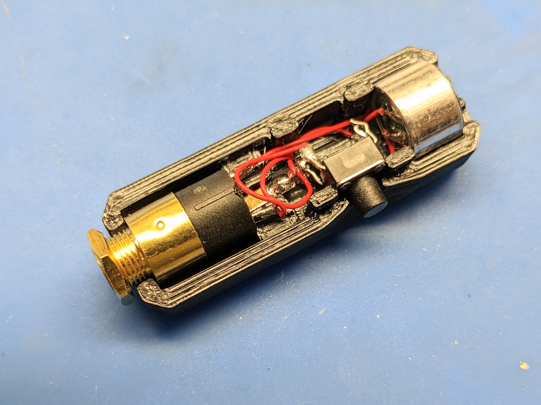
5.) Snap on top cover.
Ensure the wires are tucked in and will not be pinched, and snap on the top cover. Tighten the nut on the jack to finish the build.