Step 1: Sand PCB Edges.
Use some medium to fine grit sandpaper or a file to smooth the edges of the PCB pieces, taking off the edges that remain from panelization.
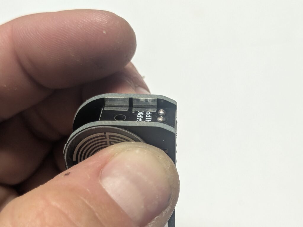
Step 2: Install the Pressure Sensors
Insert the tabs of one pressure sensor through the elongated hole at the base of one of the finger pads as shown, orienting it on the side of the finger pad PCB with the silk-screened circle.
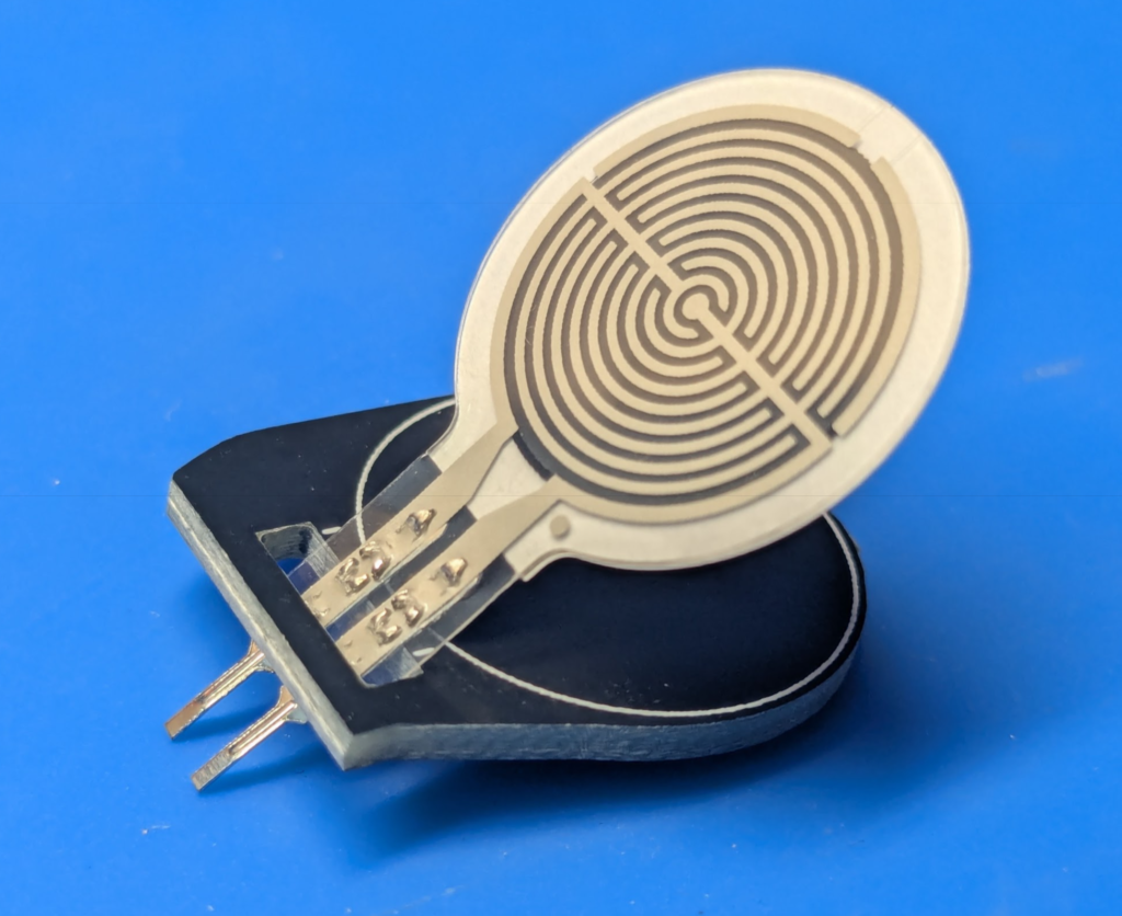
Peel the adhesive cover off of the back of the pressure sensor, center it on the circle, and press firmly into place.

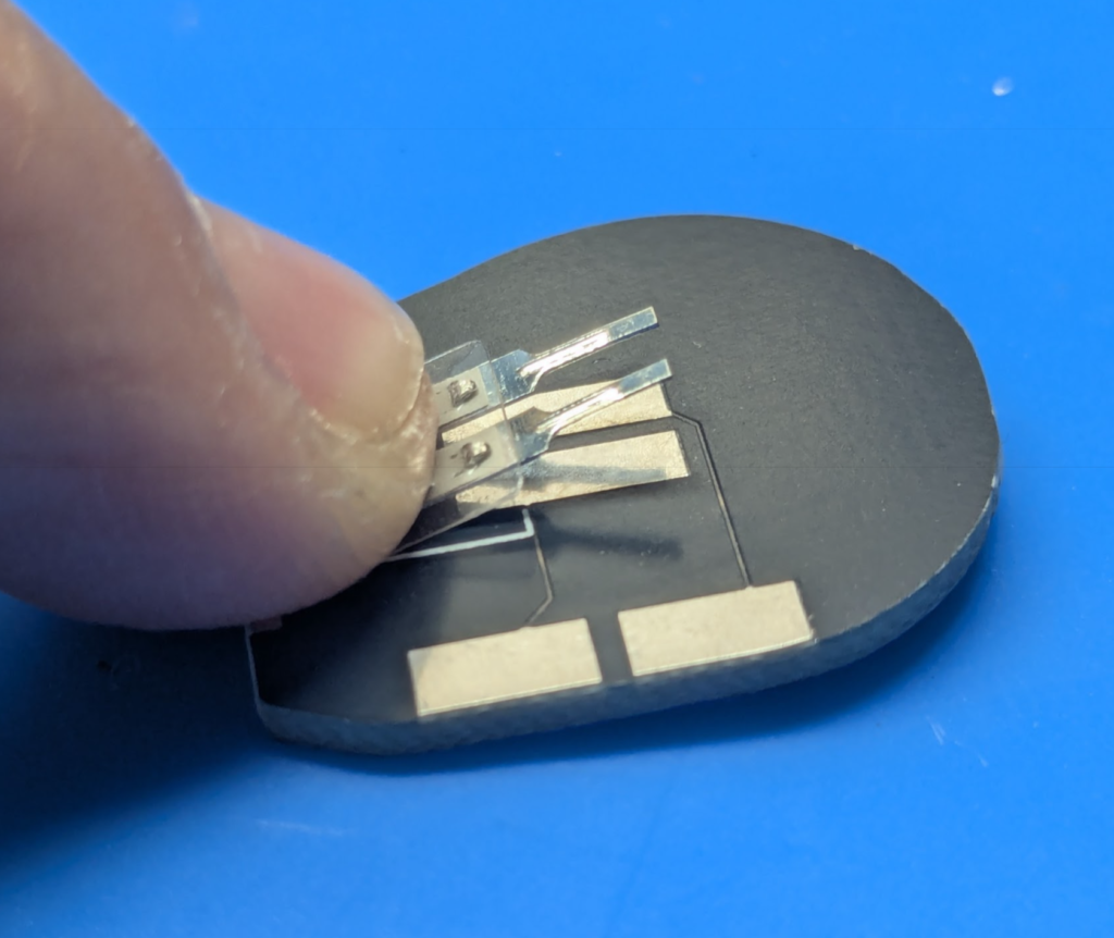
Bend the tabs over on the back side and solder to the PCB pads.
Step 3: Repeat Step 2 with the other finger pad.
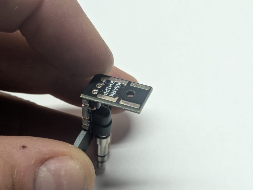
Step 4: Install the Header Pins
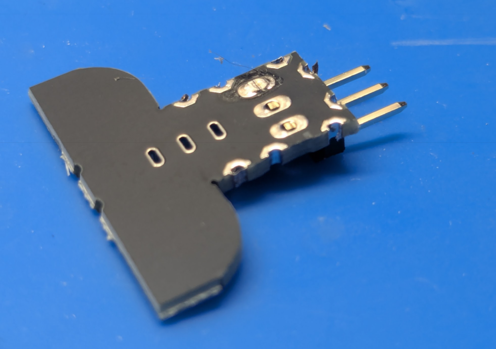
Install the header pins to the silkscreened side of the base-board with the bent leads on the base-board side as shown.
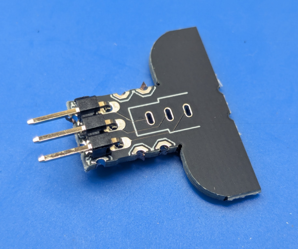
Solder one pin to secure it, then ensure the bracket is flush and flat to the board. If not, press it together and re-flow the single solder joint.
Once good positioning is confirmed, trim the pins flush and solder the other two pins.
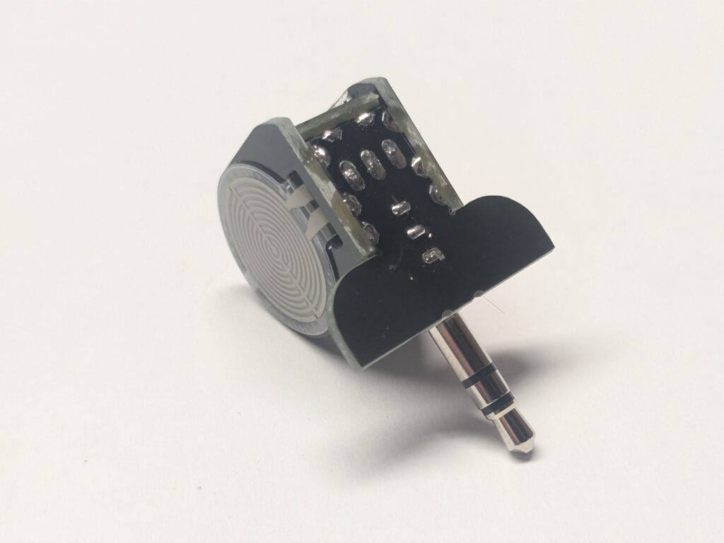
Step 5: Install the 3.5mm Plug
Place the 3.5mm plug into the base board and plug it into the KH1 to use it as a fixture as shown.
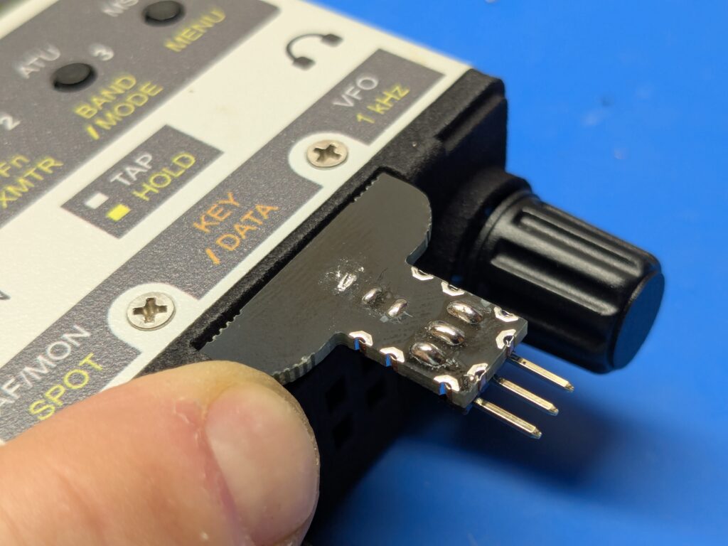
Solder one pin, confirm the board is flush, trim the pins flush, and solder the two remaining pins.
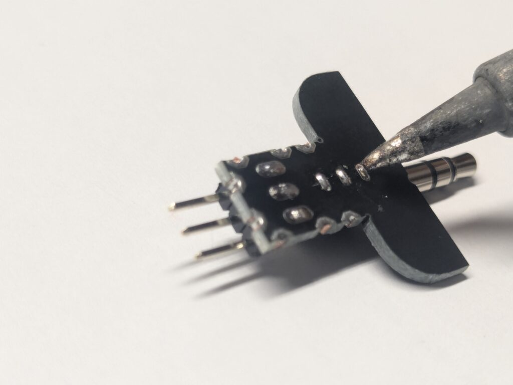
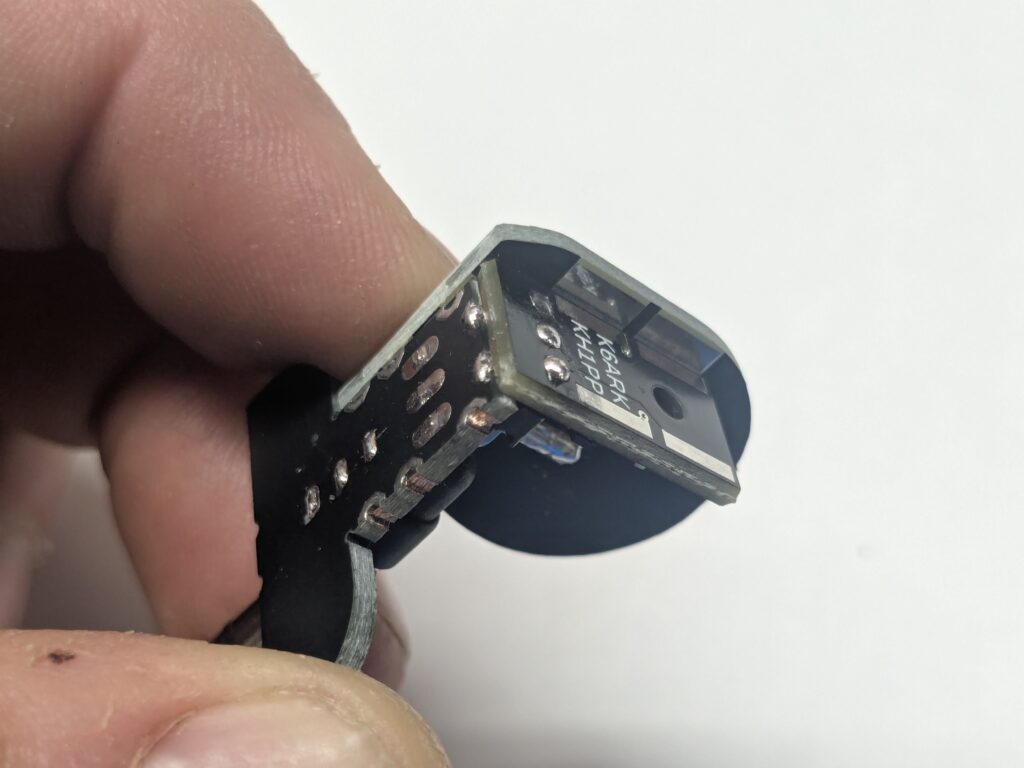
Step 6: Solder the Main Board
Position the main board onto the header pins as shown. Solder one pin and adjust carefully to achieve a 90 degree angle between the two boards. Trim the pins and solder all three completely.
Solder the pads at the board edges. These are not critical, but provide a bit more mechanical strength.
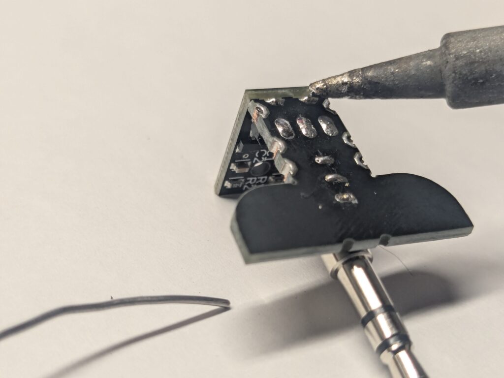
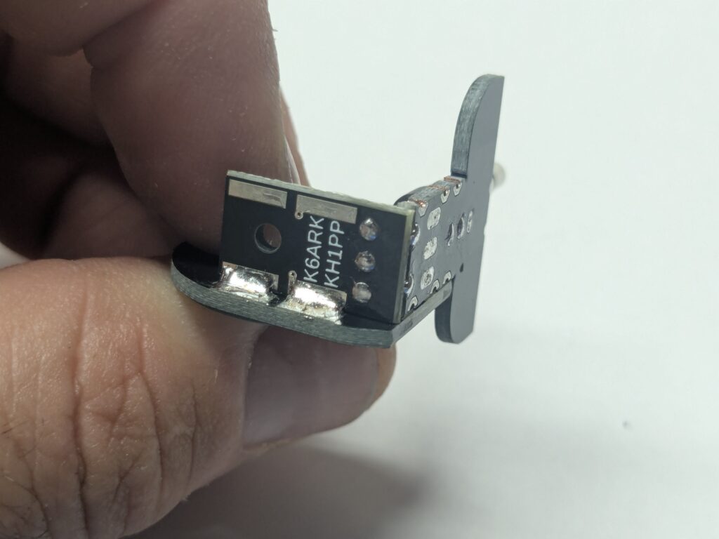
Step 7: Solder the Finger Pads
Position one finger pad on the side of the assembly, aligning the solder pads, and positioning the bottom edge flush with the bottom of the board. Solder the pads as shown.
CAUTION: The board can get fairly hot during this process so be careful not to burn your fingers.
Solder the second finger pad onto the assembly.
Solder all board edge pads on the bottom of the assembly. These are not critical for electrical function but add a bit of mechanical strength.
Step 8: Install the 3d printed cover.
Position the 3d printed cover and install the screw to secure it in place.
CAUTION: Do not overtighten the screw or it may cause the solder pads to fail.