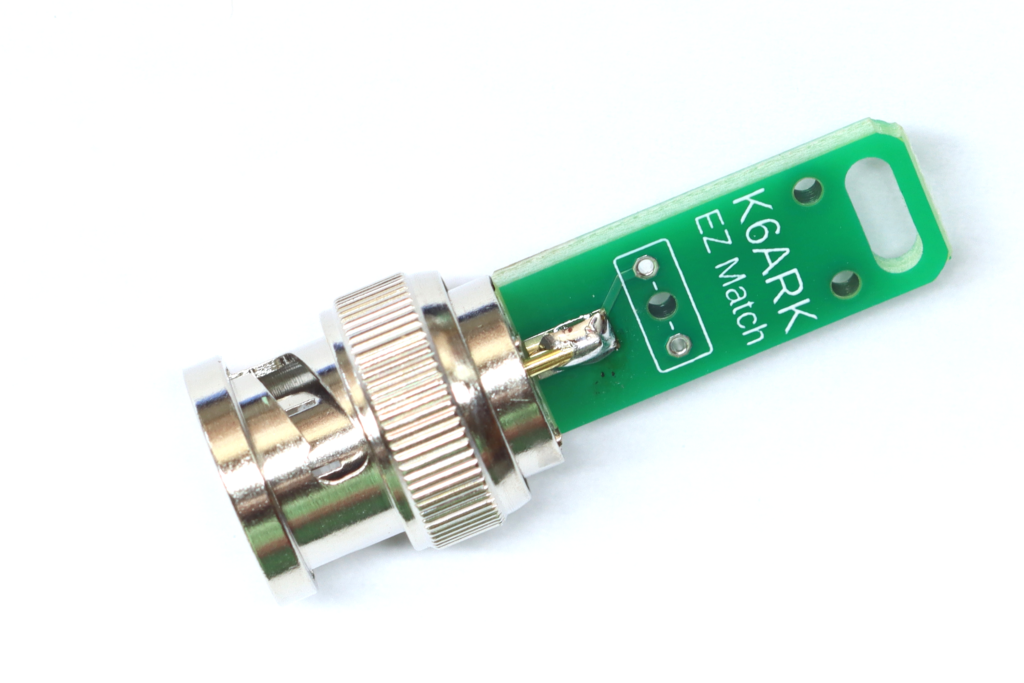
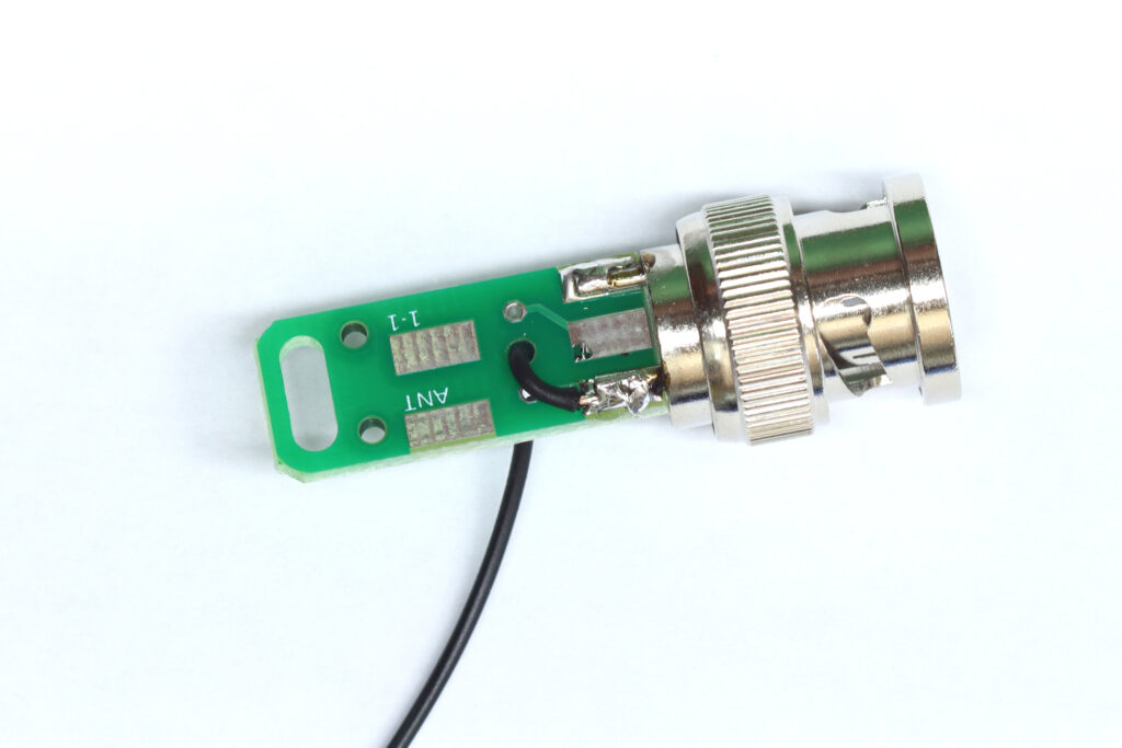
Step 1: Install PCB onto connector.
Clip two of the adjacent ground lugs off of the BNC connector and position the PCB onto the BNC.
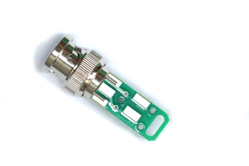
Orient the board so the single rectangular solder pad on the “K6ARK EZ Match” text is in contact with the BNC center pin conductor.
Solder the center conductor and ground lugs to the PCB pads.
Step 2: (Optional) Install counterpoise wire.
Note: I consider the counterpoise to be optional. It can help generate more consistent SWR if you include a 1/20 wavelength (i.e. 6.5 ft for 40 m) counterpoise in your antenna system.
Cut the length of Poly Stealth wire roughly in half.
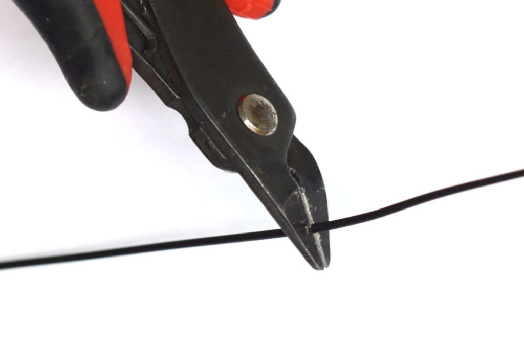
Strip about ⅛” of insulation from the end of each wire. Tin the stripped ends with solder.
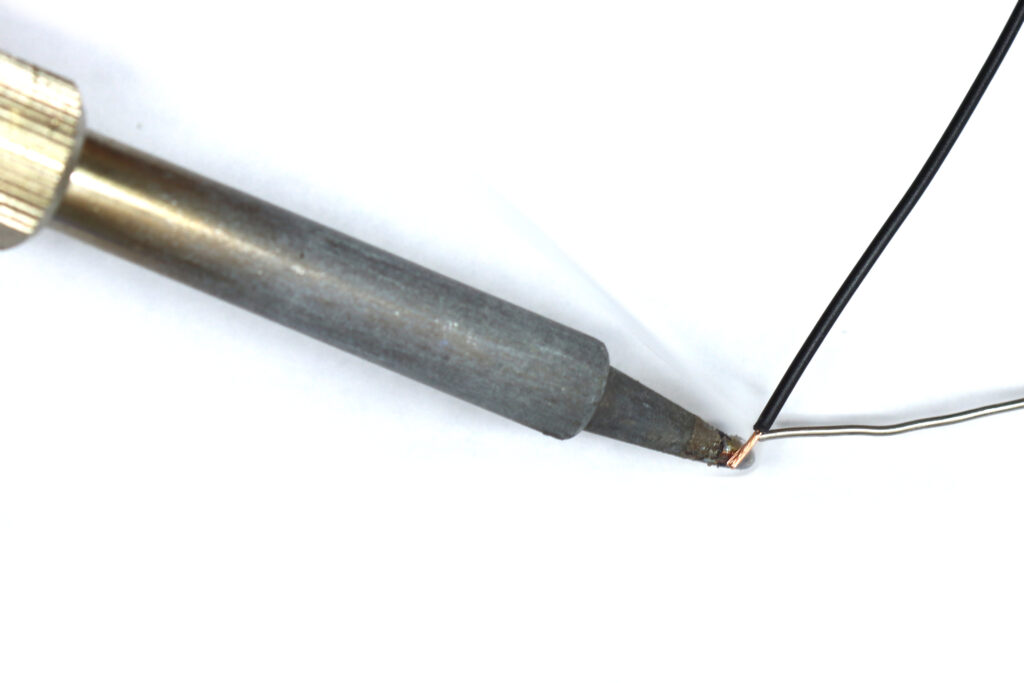
Insert one piece of wire through the strain relief hole as shown, and solder the end of the wire to one of the ground lugs.
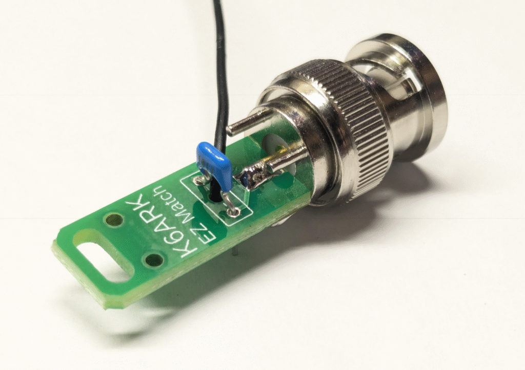
Step 3: Install the Capacitor
Install the capacitor as shown below. Solder the leads and trim them flush.
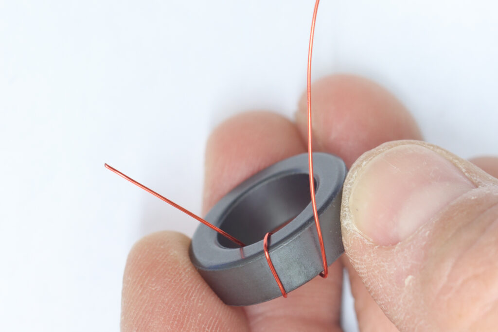
Step 4: Wind the toroid.
Begin winding the toroid as shown. Note the matching the direction of winding shown will ensure the wire leads align with the pads.
Begin winding as shown, and make 2 turns closely spaced.
After 2 turns, create a twisted stub of wire (a tap) as shown below.
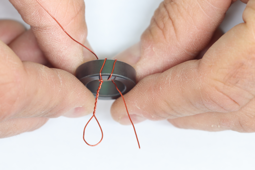
Continue winding 13 more turns for a total of 15 turns, finishing near the start of the first winding.
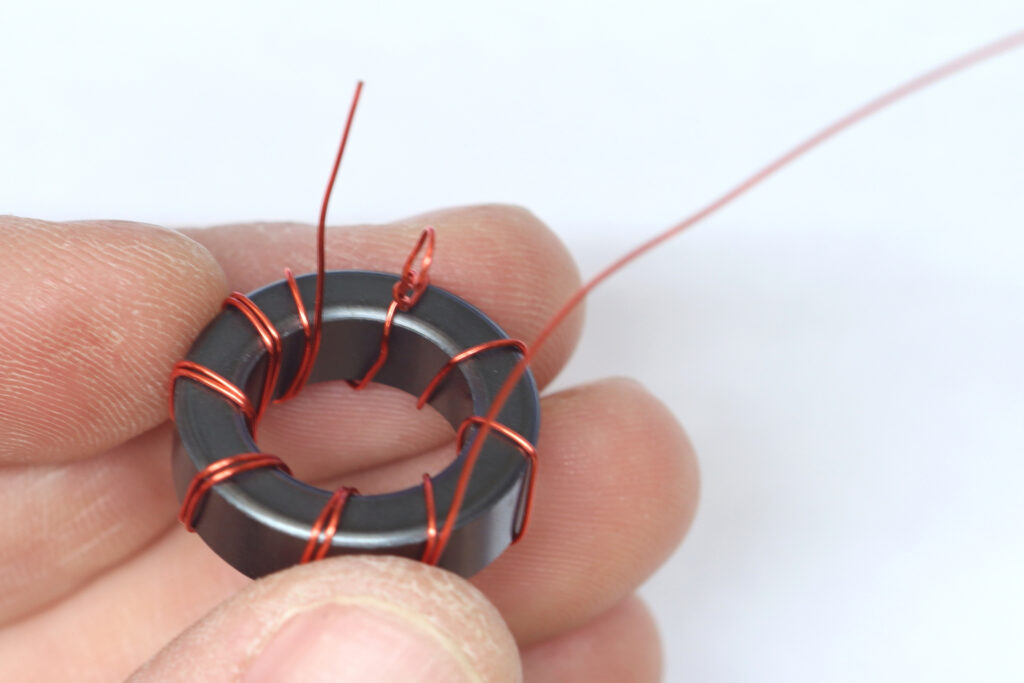
Trim the stubs to about 1/4 inch in length and tin the ends with solder, burning off the enamel.
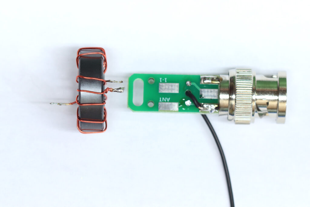
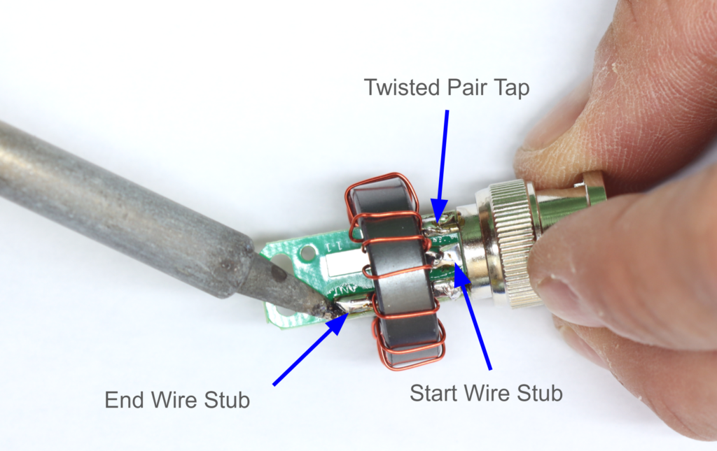
Step 5: Attach the toroid to the PCB.
Solder the toroid to the PCB as shown. The single “start” wire next to the stub is soldered to a ground lug. The twisted stub is soldered to the center solder pad on the board as shown. The “end” of the wire is soldered to the “ANT” pad.
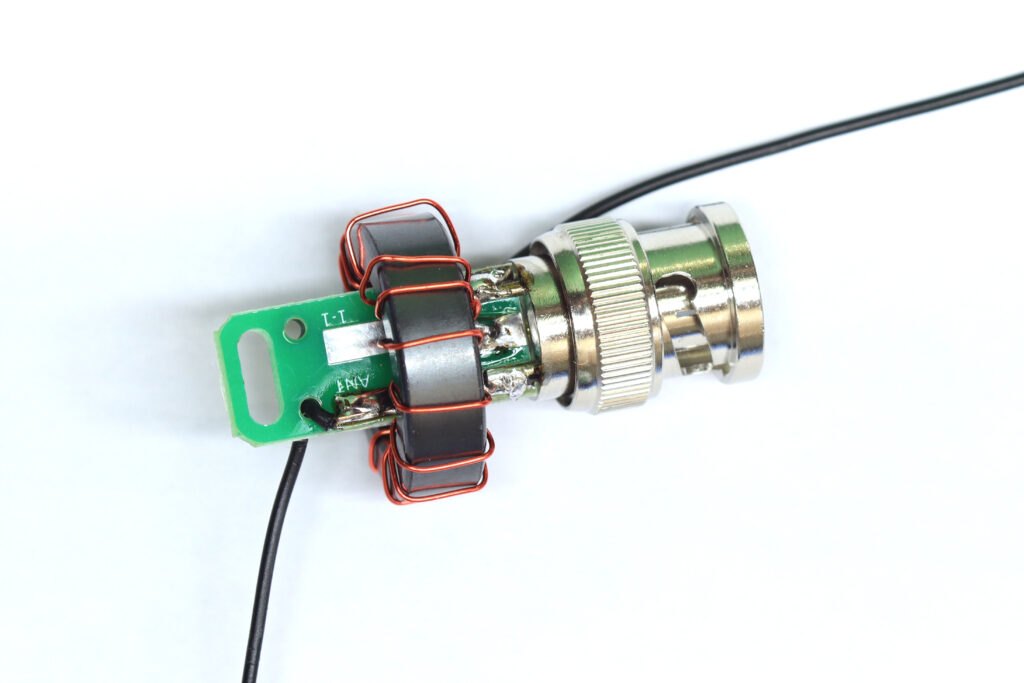
Step 6: Attach the antenna wire.
Take the other piece of black wire, or if you prefer to attach directly to your matching unit, the end of your antenna wire, and thread it through the strain relief hole near the “ANT” pad and solder the end to the “ANT” pad.
Step 7: Test the matching unit.
It’s a good idea to test the matching unit before installing the final heat shrink. Check for DC continuity between the counterpoise (if you installed one), the antenna wire, the BNC ground, and the BNC center pin. All should have ~0 ohms resistance between them. An open circuit likely means you didn’t remove enough enamel from the magnet wire.
Another good test is to attach a 2450 (or close to it) ohm resistor across the ANT and Counterpoise wires and look for a relatively low SWR across the ham bands using an antenna analyzer.
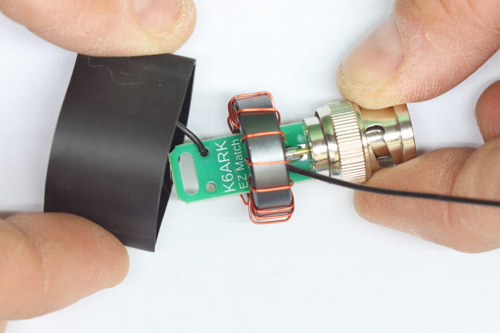
Step 8: Install the heat shrink tubing.
Place the shorter section of 1″ heat shrink tubing onto the matching unit and shrink into place as shown.
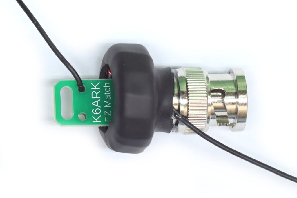
The finished unit should look like this (with your choice of connector, of course).
Step 9: Attach wire elements.
If you built the antenna for use with a counterpoise, attach a 1/20 wavelength or longer counterpoise to the counterpoise stub.
Attach a wire that is a few feet more than a half-wavelength on the lowest desired band of operation. Fold back the end to tune for resonance. Before trimming any wire, check the SWR on the resonant multiple bands (i.e. on a 40m EFHW, check 20m, 15m, and 10m). If the SWR dips are higher than the bands when 40m is properly tuned, consider adding the loading coil as described below to bring those bands into better resonance.
Step 10: Tune the higher bands.
Adding a small loading coil of about 10-12 turns on a .7” plastic former placed 6 feet from the feed point will help make a 40m half-wave resonant wire also be resonant on the higher multiples (20/15/10m). Build and tune this coil before trimming the wire.
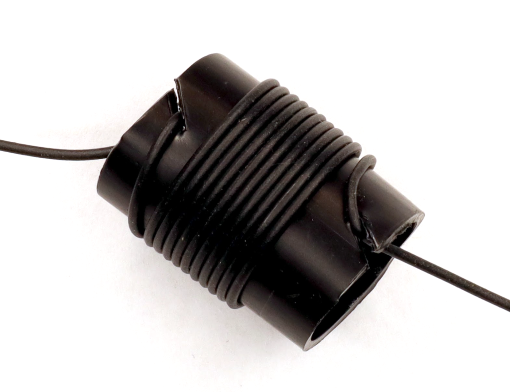
Drill or poke a small hole (preferred) in the plastic tubing to feed the wire through to secure the ends of the coil, or cut slots as shown above. Cover with tape, to secure it temporarily, then use the second piece of larger heat shrink in the kit to permanently secure the wire onto the coil.
Re-tune the remaining wire by unfolding some of the wire at the end to achieve resonance on 40m, then check resonance on the harmonics, 20m, 15m, and 10m. Adjust the coil as necessary.
If the higher bands have low SWR above the ham bands when 40m is tuned properly, you need to add inductance (additional turns) to the coil. If the SWR dips are below the higher bands when 40m is tuned, you need to subtract turns from the coil.