Step 1: Install PCB onto connector.
Clip two of the adjacent ground lugs off of the BNC connector, then position the PCB onto the BNC as shown below between the remaining lugs and center pin.
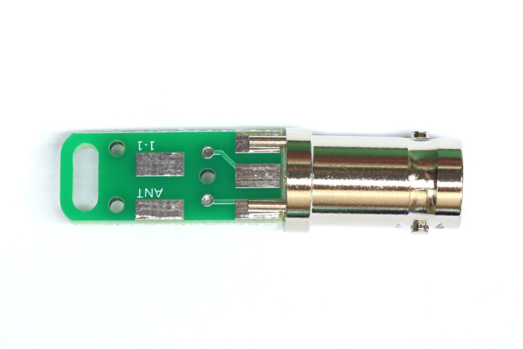
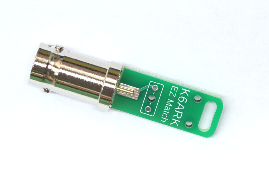
Orient the board so the single rectangular solder pad on the “K6ARK EZ Match” text is in contact with the BNC center pin conductor.
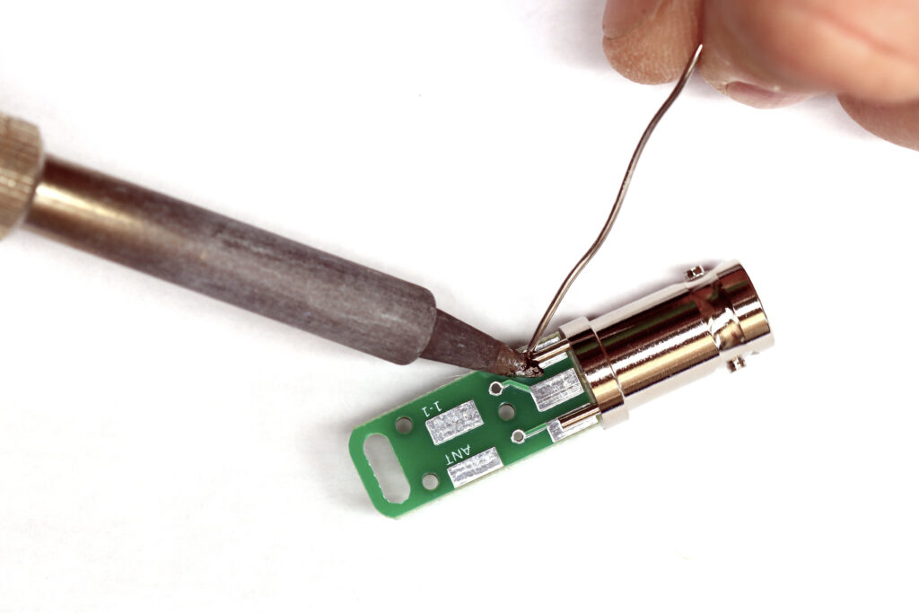
Solder the center conductor and ground lugs to the PCB pads.
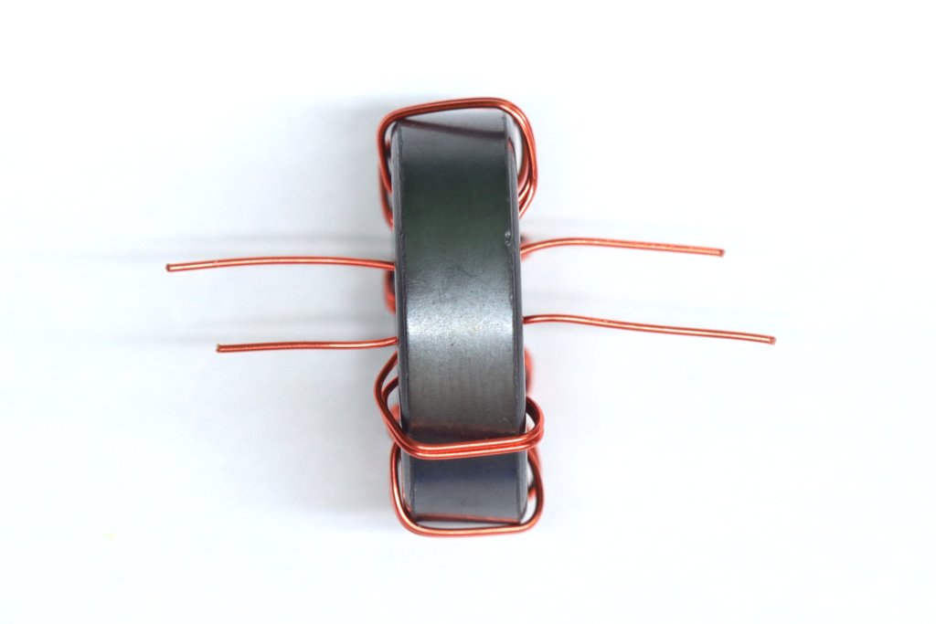
Step 2: Wind the toroid.
Fold the magnet wire in half.
Start winding the two strands around the toroid, making a total of 8 turns around the toroid. Each pass through the toroid center counts as a turn.
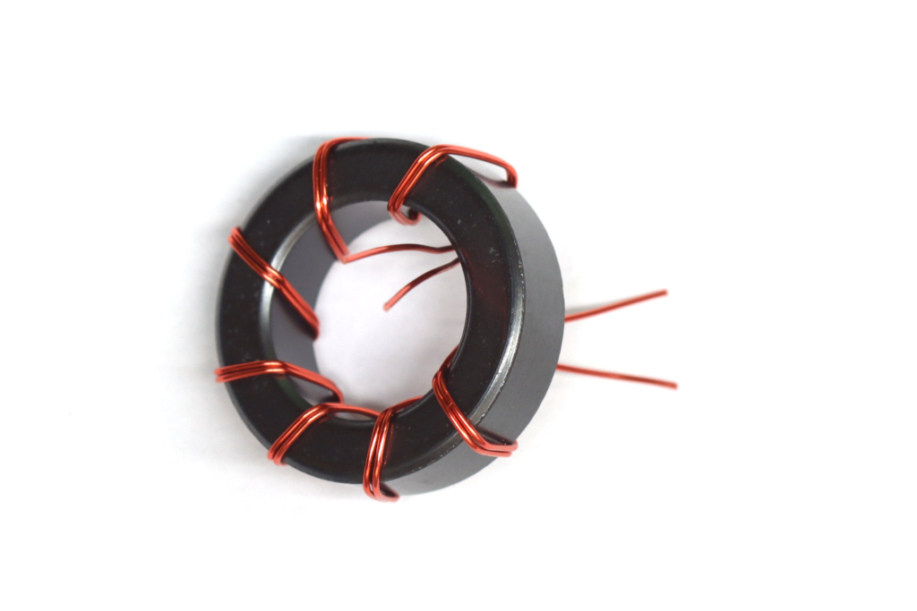
Finish the windings on on the opposite side of the toroid from where you started.
Note: If the wires cross, it is unlikely to cause any issues, but I generally try to keep them parallel.
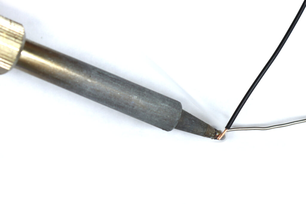
Trim the wires to about 1/4″ and tin them with solder, burning off the enamel from the ends of the wires.
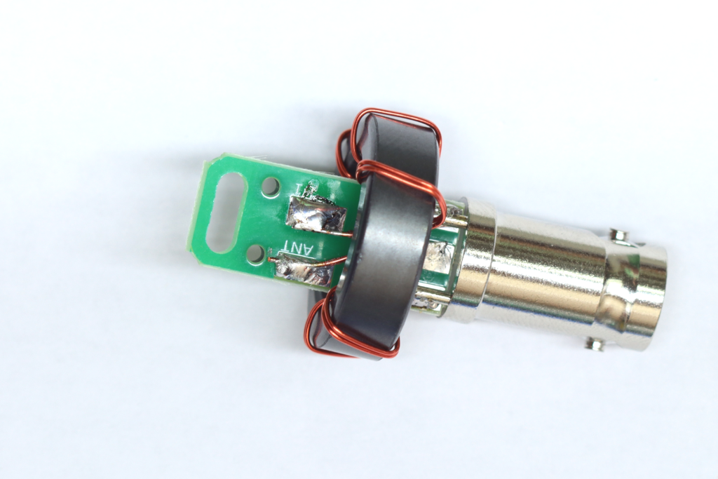
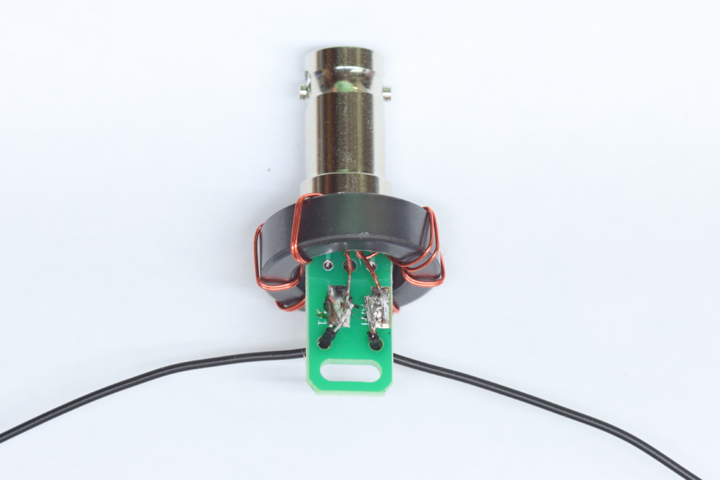
Step 3: Attach the toroid to the PCB.
Slip the toroid onto the PCB. Solder one of the BNC side magent wire stubs to the center pad, and the other to one of the ground lugs as shown.
Solder the magnet wire stubs on the other end to the “ANT” and “GND” pads.
Note: For a balanced antenna like a dipole, it does not matter which wire is attached to which pad. For a ground mounted vertical or other grounded antenna, ensure the magnet wire connected to the center pad at the BNC is connected to the “ANT” pad at the other end.
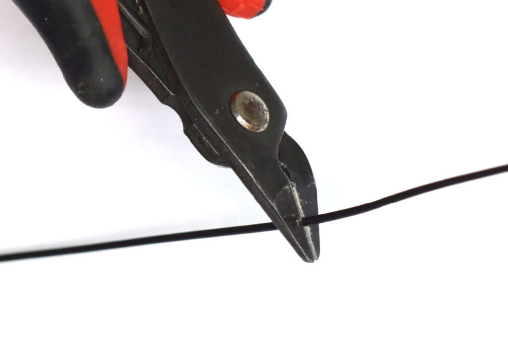
Step 4: Attach wires.
Cut the length of Poly Stealth wire roughly in half.
Strip about ⅛” of insulation from the end of each wire. Tin the stripped ends with solder.
Install one wire through the strain relief hole near the 1-1 pad, and solder to to the 1-1 pad.
Install the other wire through the strain relief hole near the ANT pad and solder to the 1-1 pad.
Step 5: Test the matching unit.
Check for continuity between the BNC ground and both antenna wires. One wire should have continuity (close to 0 ohms DC resistance) and the other should be an open circuit (infinite ohms). Do the same test from the BNC center pin to the two antenna wires. You should find the opposite of the last test.
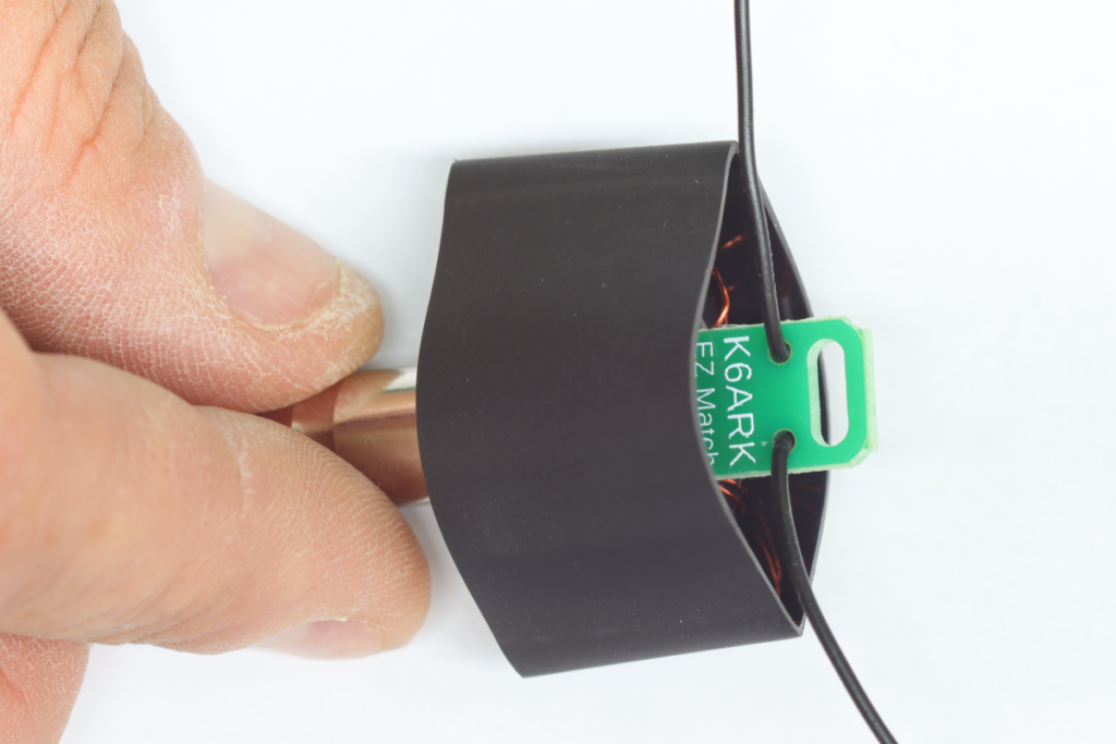
Step 6: Install the heat shrink tubing.
Place the shorter section of 1″ heat shrink tubing onto the matching unit and shrink into place as shown.
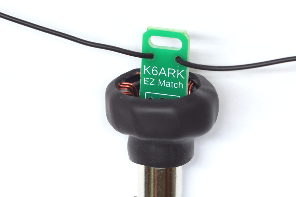
The finished unit should look like this (with your choice of connector, of course).
Step 7: Attach wire elements.
Attach wire elements slightly longer than 1/4 wavelength, hoist it all in the air, and trim or fold back the wires to tune.