Step 1: Install PCB onto connector.
Clip two of the adjacent ground lugs off of the BNC connector and position the PCB onto the BNC.
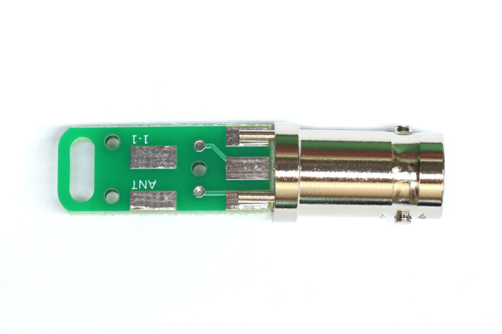
Orient the board so the single rectangular solder pad on the “K6ARK EZ Match” text is in contact with the BNC center pin conductor.
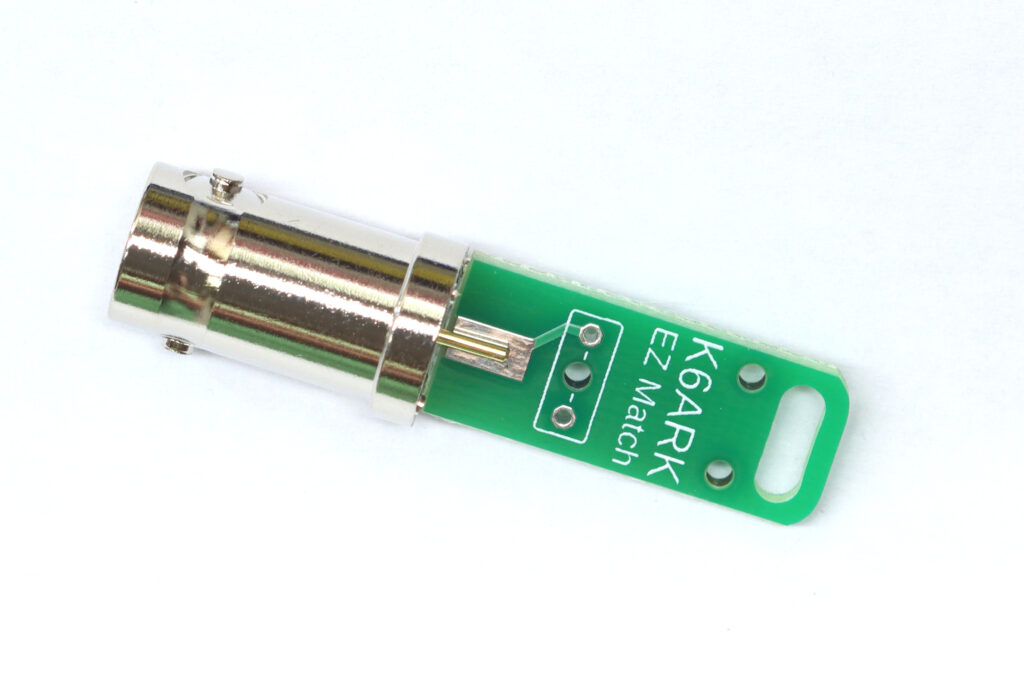
Solder the center conductor and ground lugs to the PCB pads.
Step 2: Decide how you want your counterpoise attached.
Note: The standard build for the 4:1 unun has the counterpoise wire exit the top of the matching unit. If you prefer to have the counterpoise wire exit the top of the unit, take a look at Step 3 in the 9:1 unun build instructions.
Top counterpoise. Go to the next step.
Bottom counterpoise. Install per step 3 in 9:1 unun instructions.
Step 3: Wind the toroid.
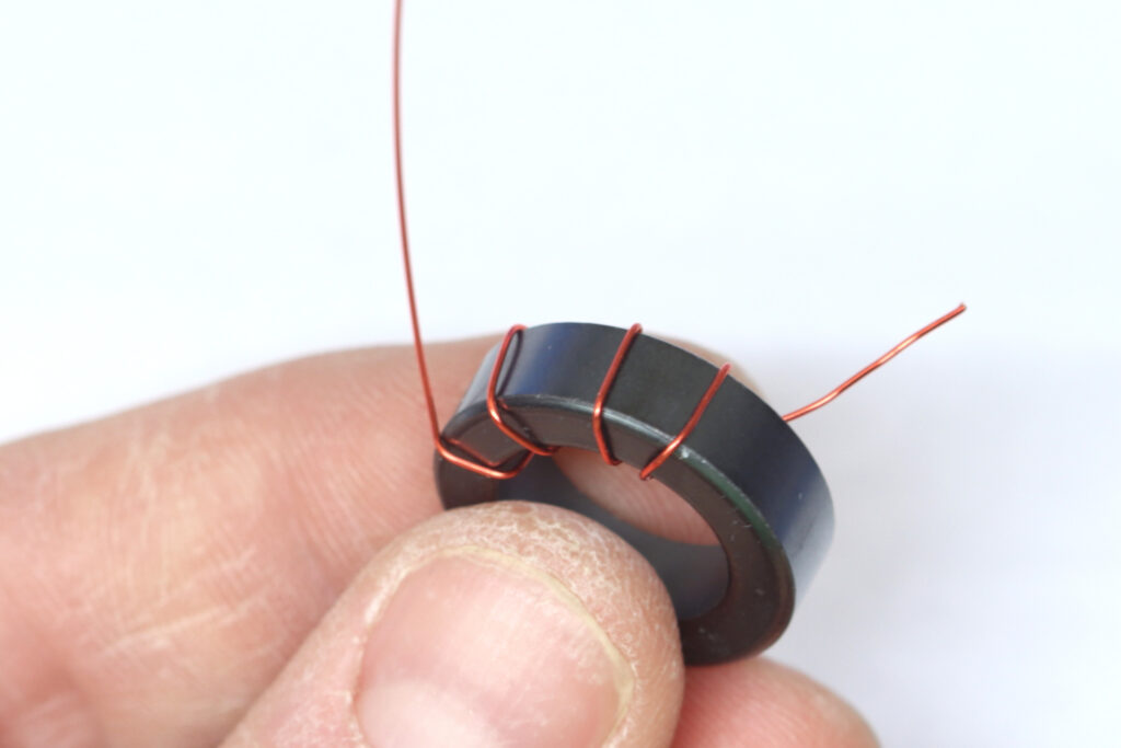
Begin winding the toroid as shown. Note the matching the direction of winding shown will ensure the wire leads align with the pads.
Begin winding as shown, and make 8 turns all the way around the toroid with wide spacing.
After 8 turns, create a twisted stub of wire, a tap, just before reaching the stub of wire where you started winding.
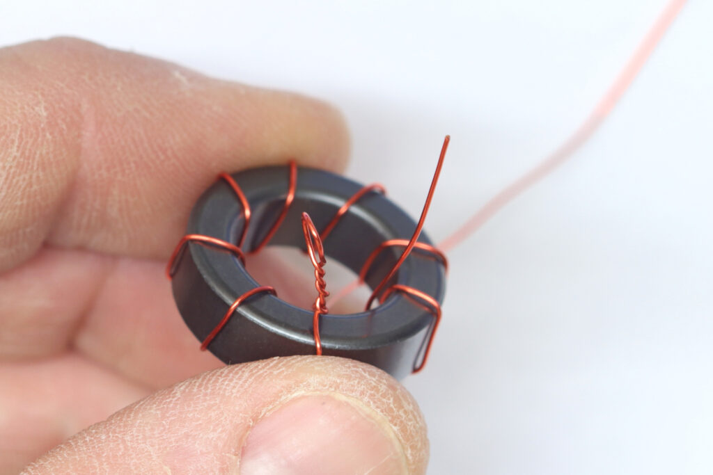
After creating the stub, continue wrapping 8 more turns around the toroid.
Note: I usually try to wrap the wires next to the 8 turns on the previous lap around the toroid so it’s easy to keep count, and it looks nice, but it is not necessary for the transformer to function properly.
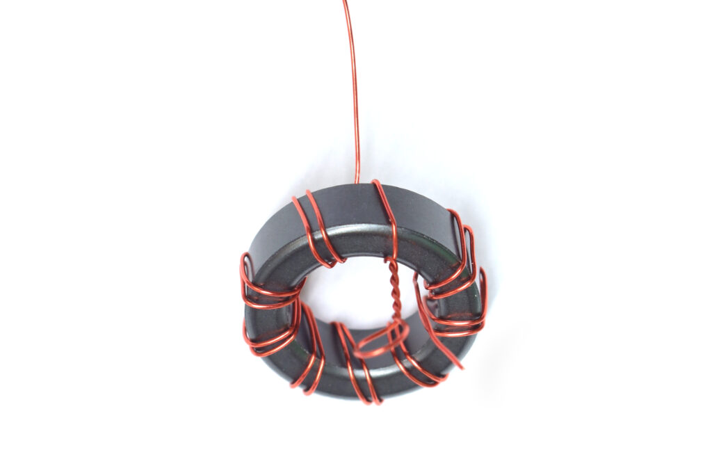
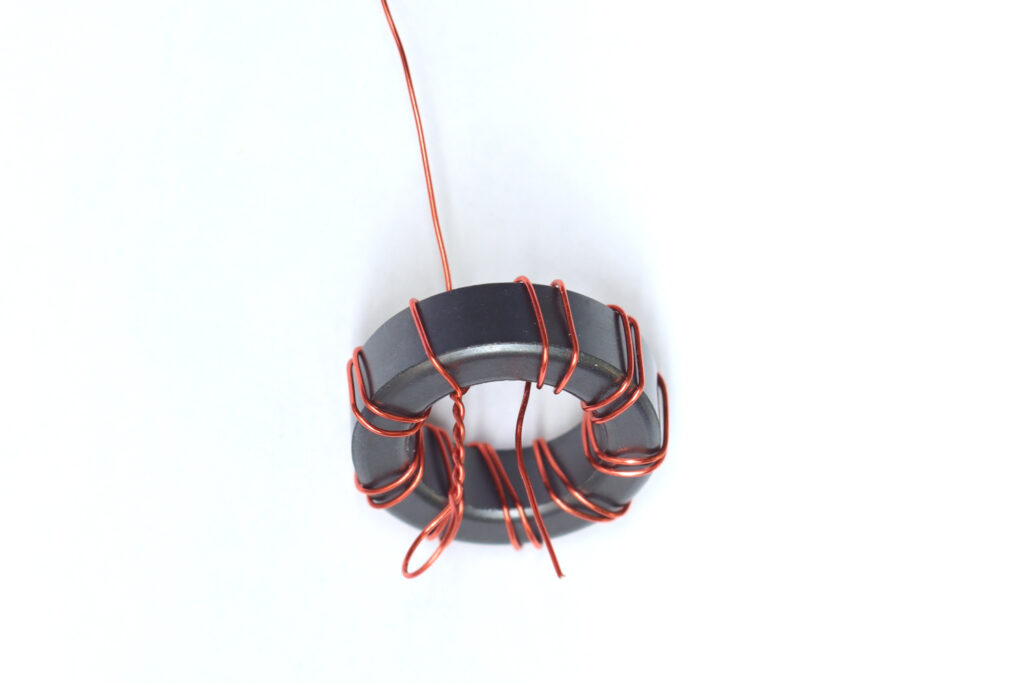
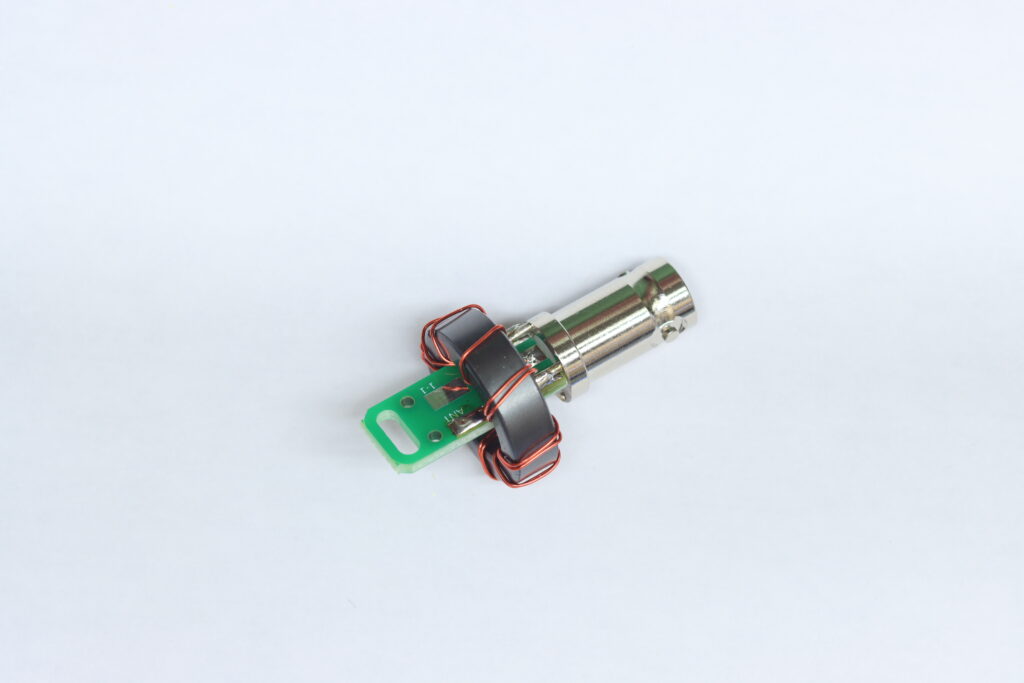
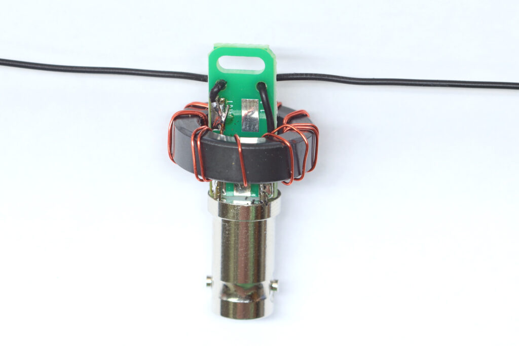
The final toroid should look like this.
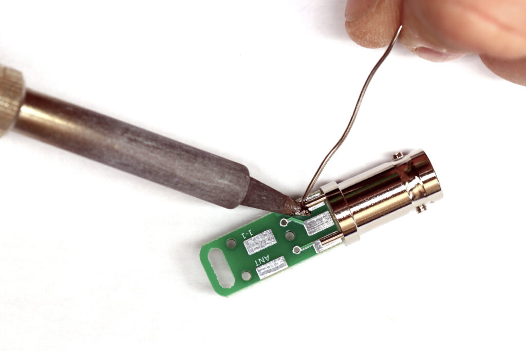
Step 4: Attach the toroid to the PCB.
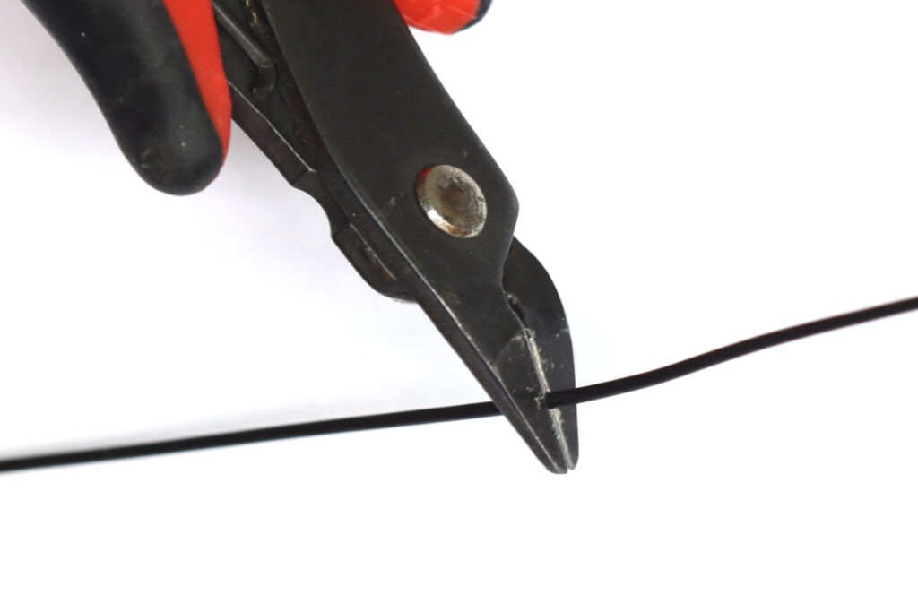
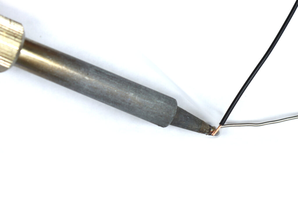
Trim the magnet wire ends to about 1/4″ in length. Tin the magnet wire ends with solder, burning off the enamel with a hot iron.
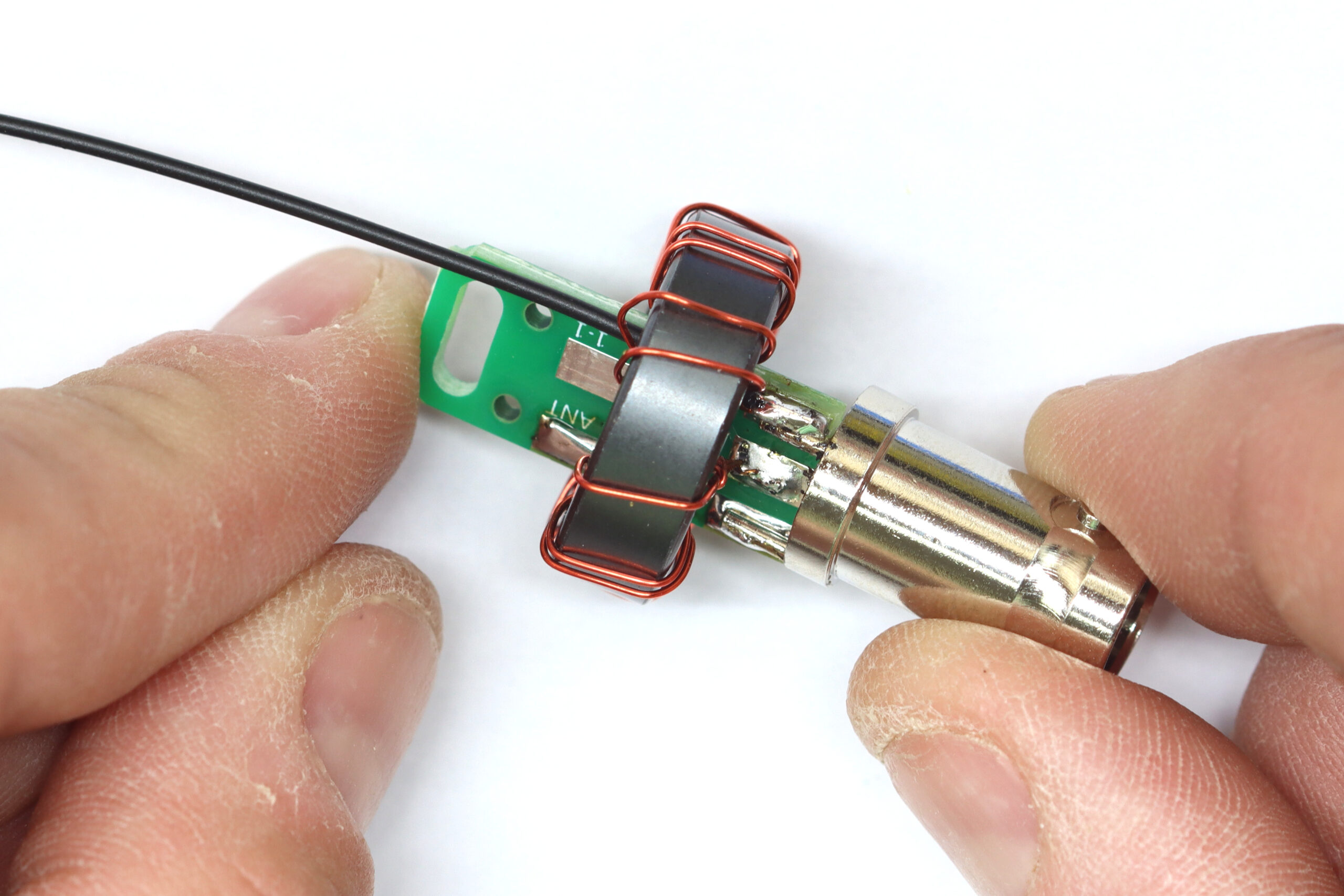
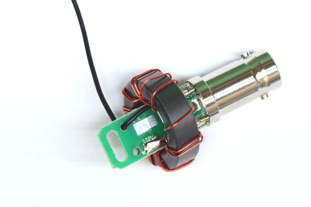
Solder the toroid to the PCB as shown. The single “start” wire next to the stub is soldered to one of the ground lugs.
The twisted stub is soldered to the center solder pad on the board as shown. The single “end” of the wire is soldered to the “ANT” pad.
Note: Male BNC and 49:1 shown below, but 4:1 unun is soldered the same way.
Be careful not to short the center pad or wire to the case of the BNC.
Step 5: If you have not already installed the counterpoise, install it now.
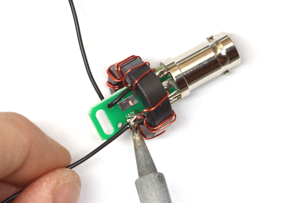
Cut the length of Poly Stealth wire roughly in half.
Strip about ⅛” of insulation from the end of each wire. Tin the stripped ends with solder.
Install the counterpoise wire by soldering the tinned end to one of the ground lugs.
Insert the end of the counterpoise wire through the strain relief hole near the 1-1 pad.
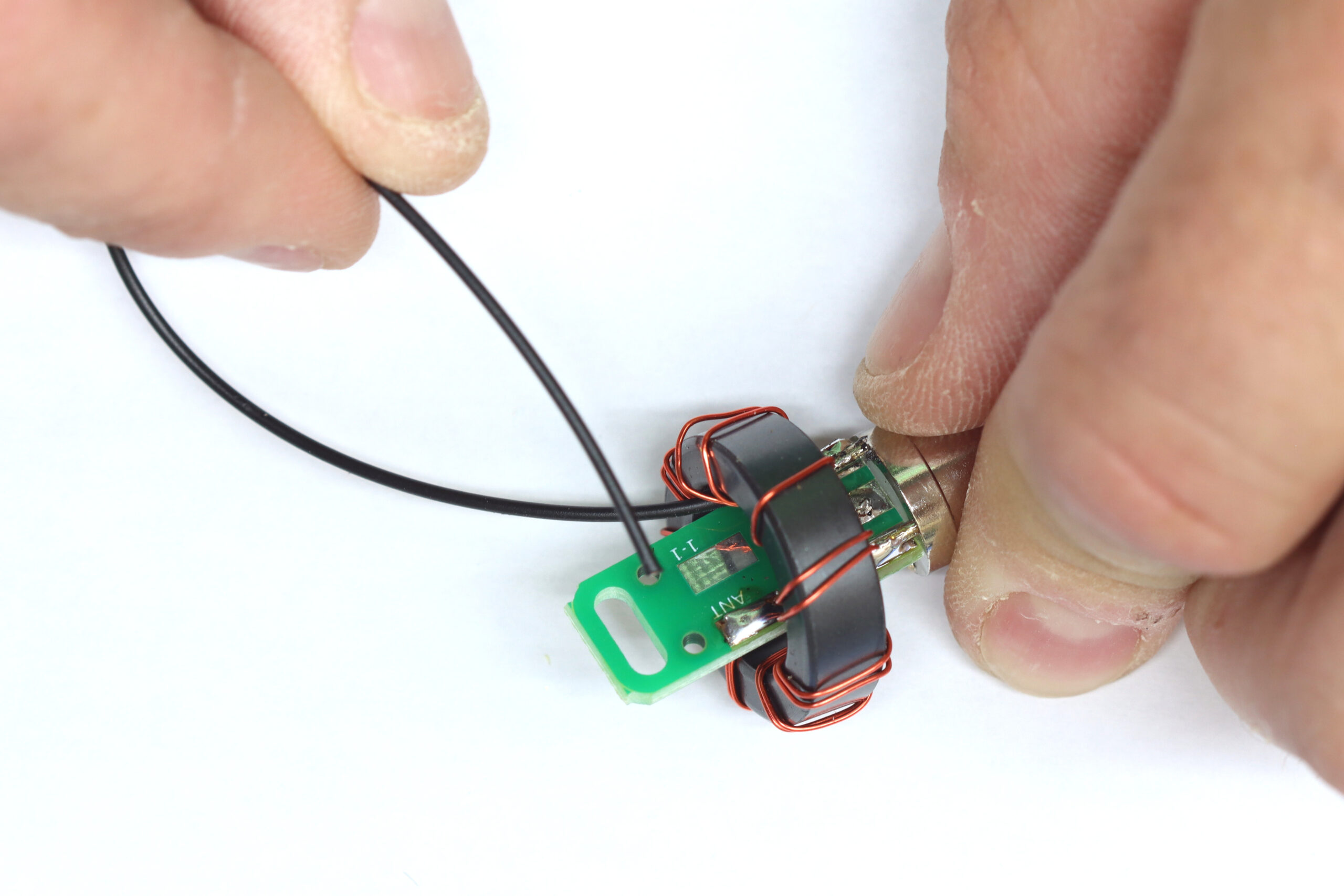
Gently pull the wire through the hole to position it as shown.
Step 6: Attach the antenna wire.
Solder your antenna wire to the “ANT” pad as shown. Some may find it easier to thread it through the strain relief hole before soldering.
If you did not already, thread the wire through the hole and gently work it into the position shown below.
Step 7: Test the matching unit.
It’s a good idea to test the matching unit before installing the final heat shrink. Confirm continuity (close to zero resistance) between the BNC ground, center pin, counterpoise, and antenna wire.
You can also attach a 200 ohm resistor across the counterpoise and antenna wire and confirm that SWR is relatively low across the ham bands with an antenna analyzer.
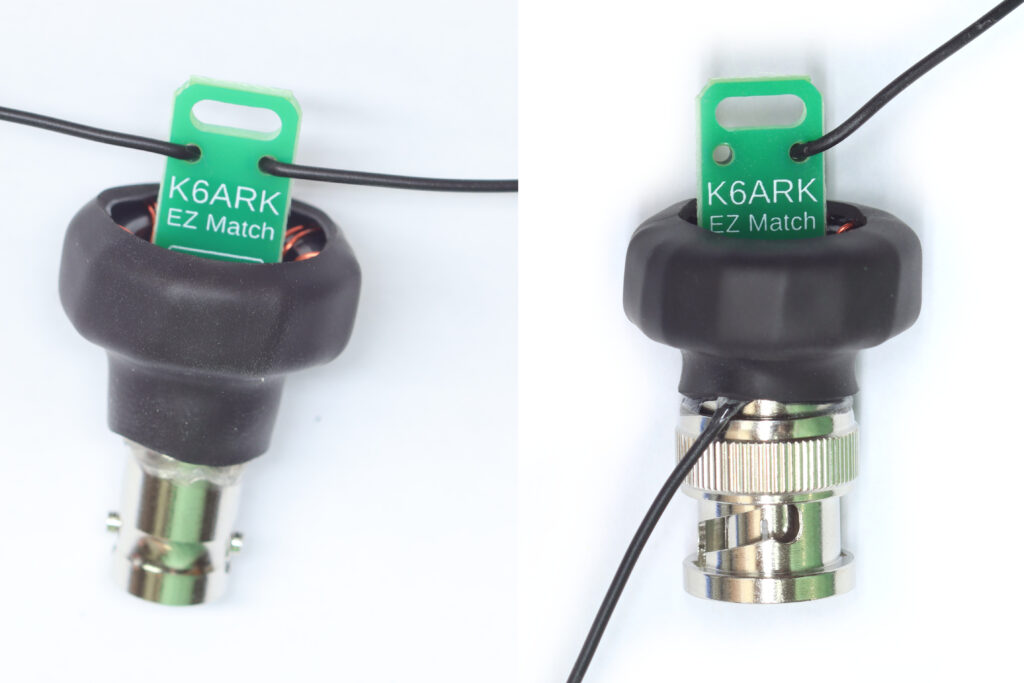
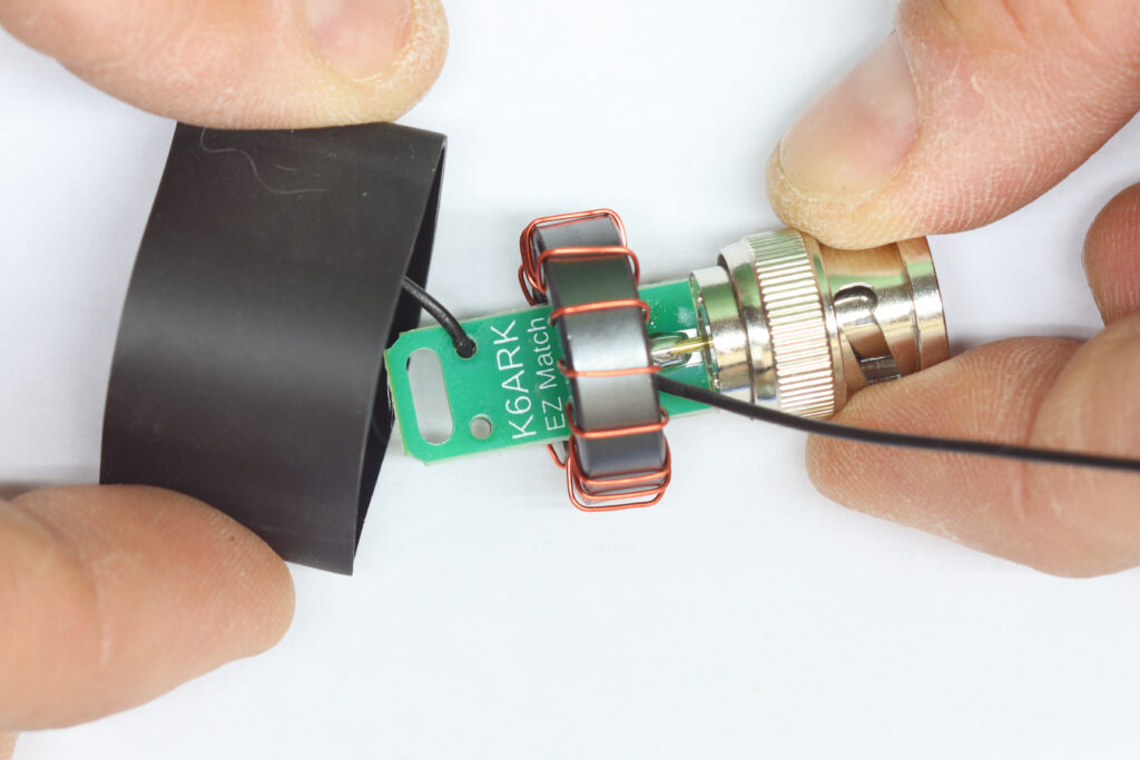
Step 8: Install the heat shrink tubing.
Place the shorter section of 1″ heat shrink tubing onto the matching unit and shrink into place as shown.
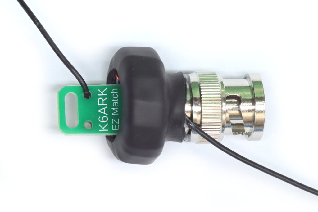
The finished unit should look like this (with your choice of connector, of course).
Step 9: Attach wire elements.
Attach a 17 ft counterpoise to the shorter wire stub (C-POISE). Attach a “random” length wire to the longer wire stub (ANT) – I recommend 41 ft which should be usable on 10 m through 80 m with a KX2, KX3, T-1 tuner, or Xiegu X5105.