This slick design utilizes shock-corded elements for rapid deployment and still offers over 4 dBd of forward gain. A 50 ohm feed makes matching simple, and with a weight under 5 oz, you’ll never leave it at home.
Design Details
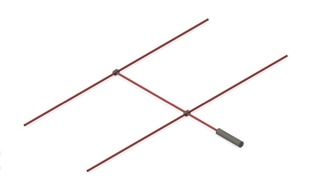
This slick little 2 element yagi will get you on the air quickly, and help you reach out further for more contacts. 4.15 dBd (6.3 dBi) forward gain, and 10 dB front to back ratio helps grab the contacts you want, and reject interference.
Here’s everything you need to build your own.
Performance

Bill of Materials
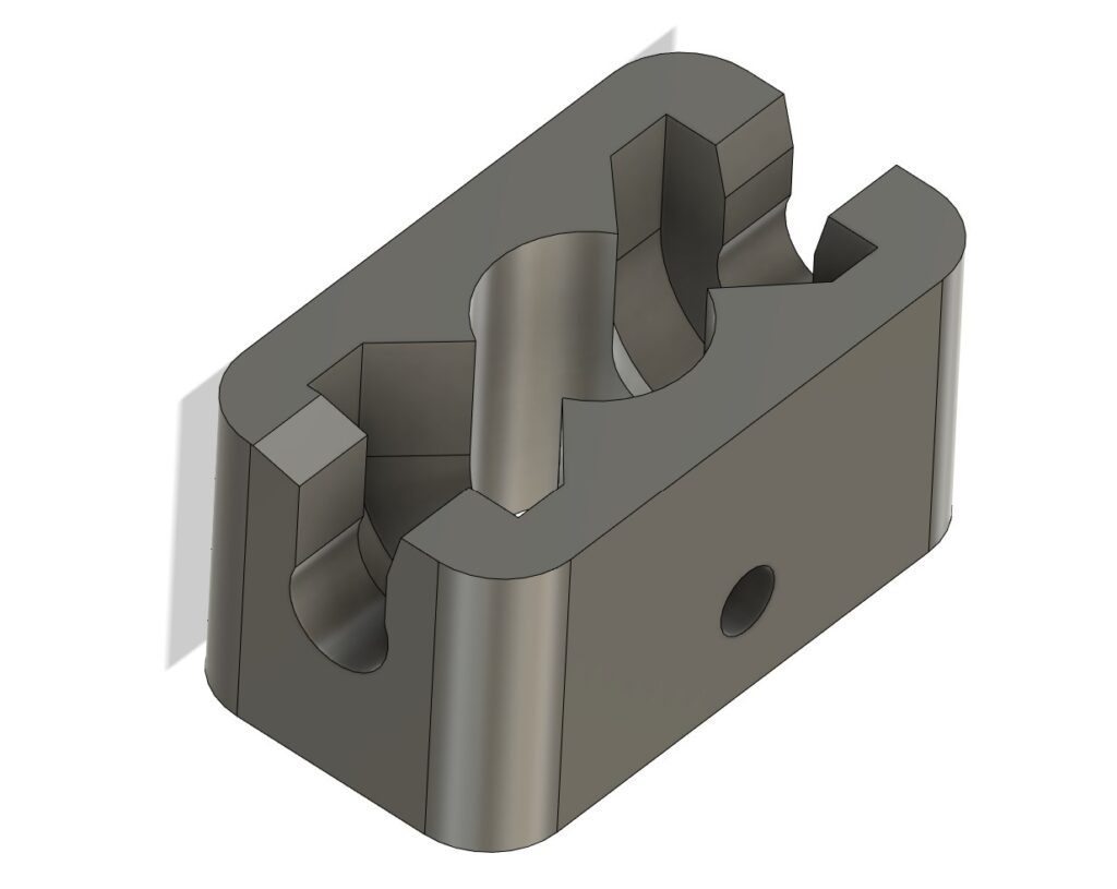
2 pieces: 3d Print Yagi Bracket yagi-bracket.STL on Printables.com
4 pieces: 8-32 x 3/4″ Stainless Screws
2 pieces: M3 Set Screws
8 pieces: Arrow Shaft Threaded Inserts
5 pieces: Aluminum Arrow Shafts
4 pieces: 1/8″ Shock Cord
6 inches: 1/4″ ID Foam Tube
1 piece: Coax with Connector
2 pieces: #8 Ring Termial
* The links above are Amazon Affiliate links. They cost you no more, but give me a small kick-back for my effort.
Construction
1. Print the yagi-bracket.STL files
Print two yagi brackets using PETG, ABS, or Nylon.
2. Cut the Elements
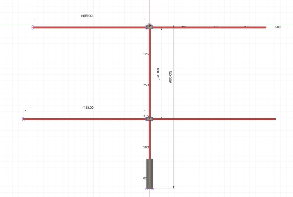
Cut two arrow shafts to 455 mm, cut two to 493 mm, and cut one to about 660 mm (not critical) for the boom. A pipe/tubing cutting tool makes cutting the elements very easy.
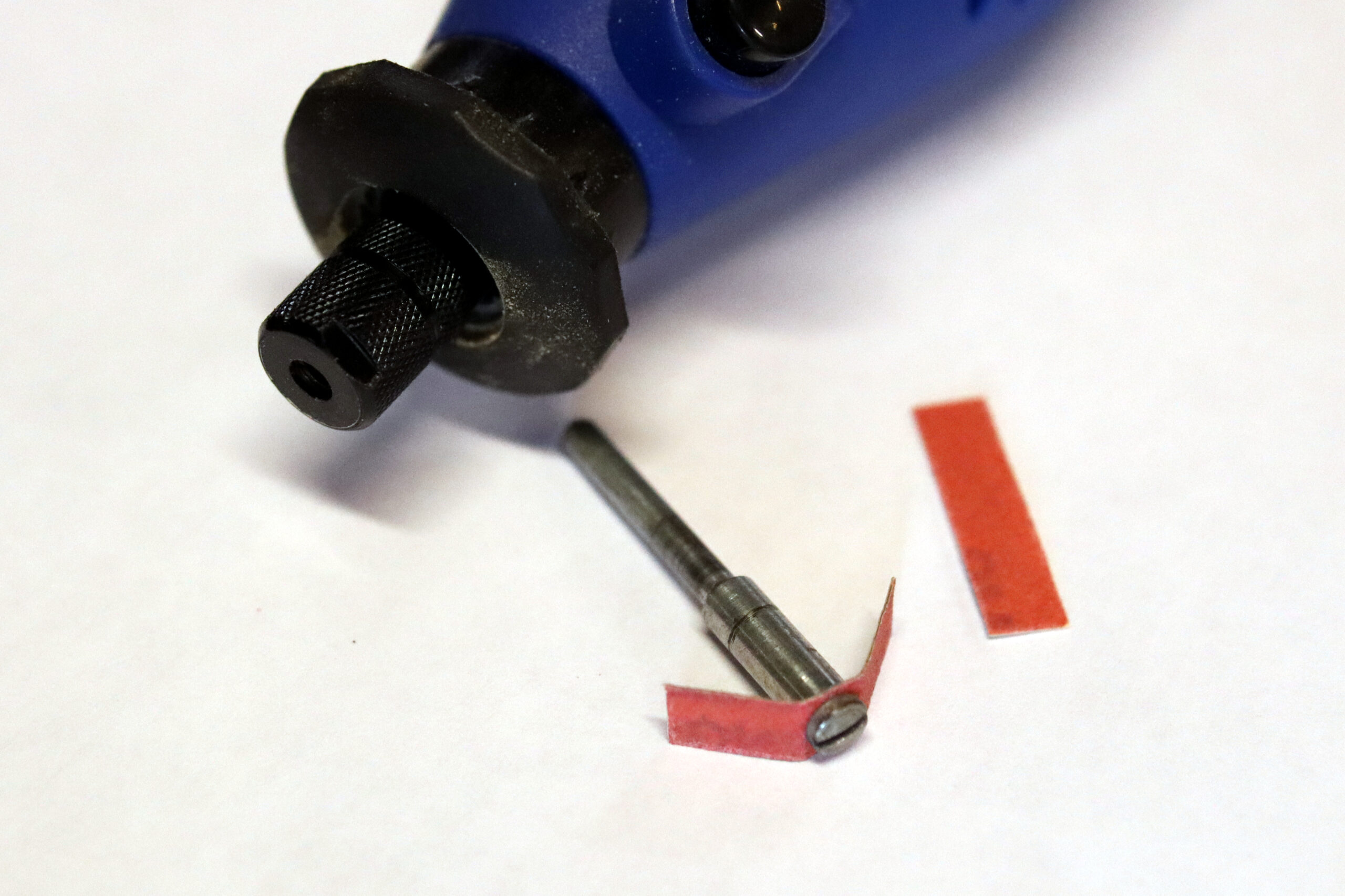
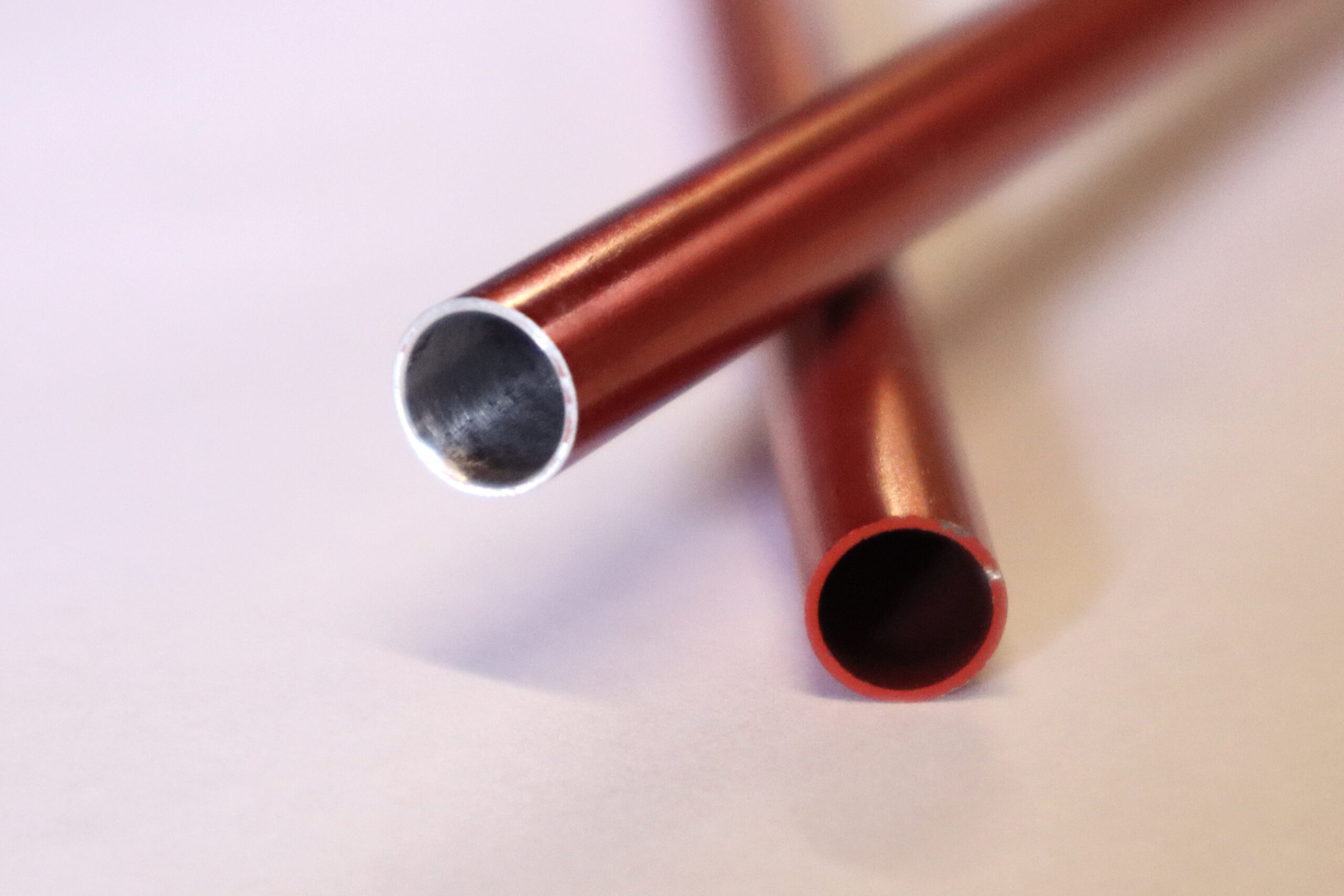
3. Remove Anodize Coating
Remove the anodize coating from the end and interior of the arrow shaft that will be attached to the bracket. Use a dremel tool with a strip of sandpaper attached to remove the inner coating, if possible. 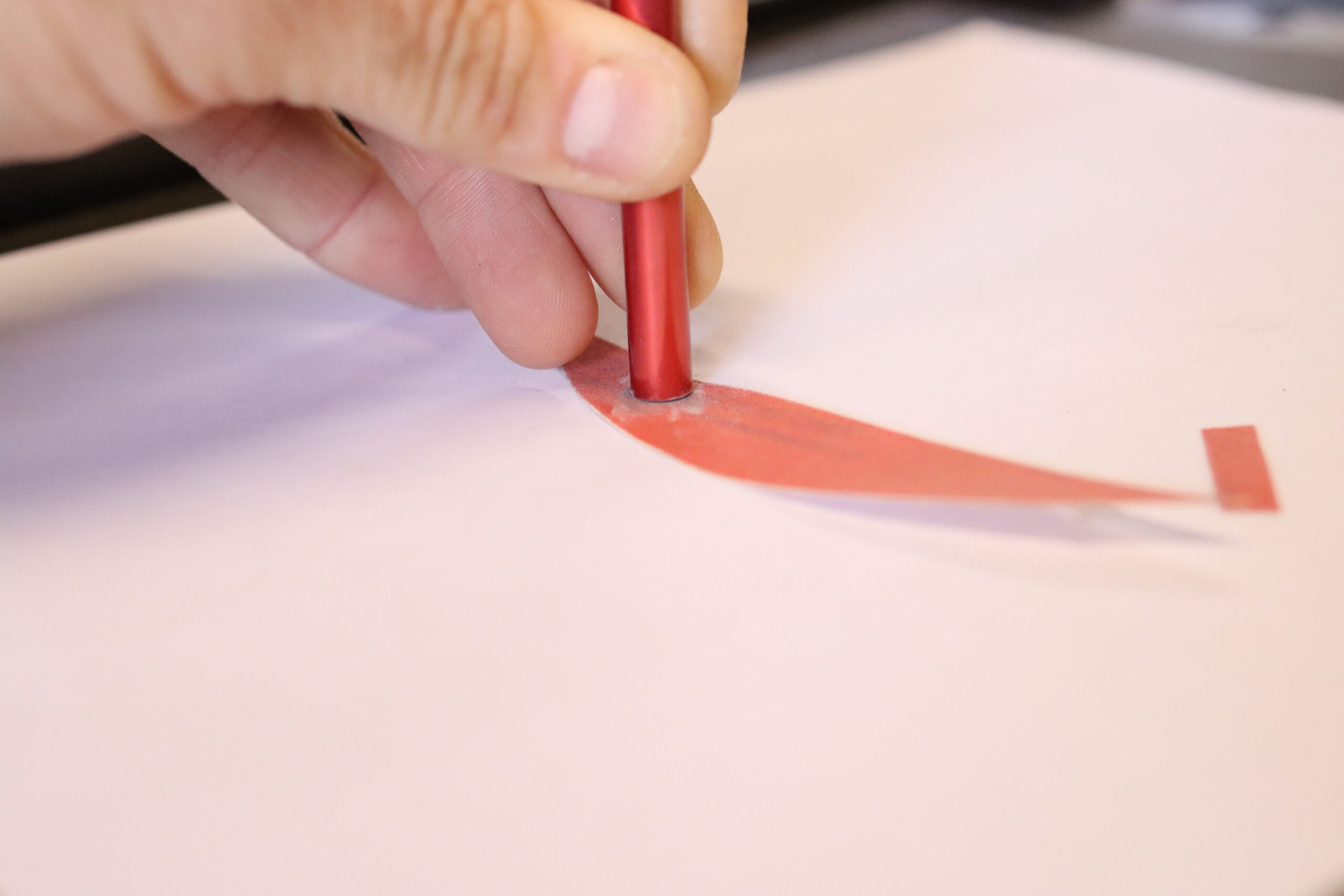
4. Cut Shock Cord
Cut 4 pieces of shock cord approximately 10 cm shorter than each element.
5. Prepare the Feed Line
Cut the coax section in half. Optional: if you have FT82-43 or similar toroid, make 4-8 turns through the toroid to form a choke near the cut end of the coax. Leave enough room to strip an inch or so of coax and crimp or solder the ring terminals into place on the ends of the center conductor and shield. 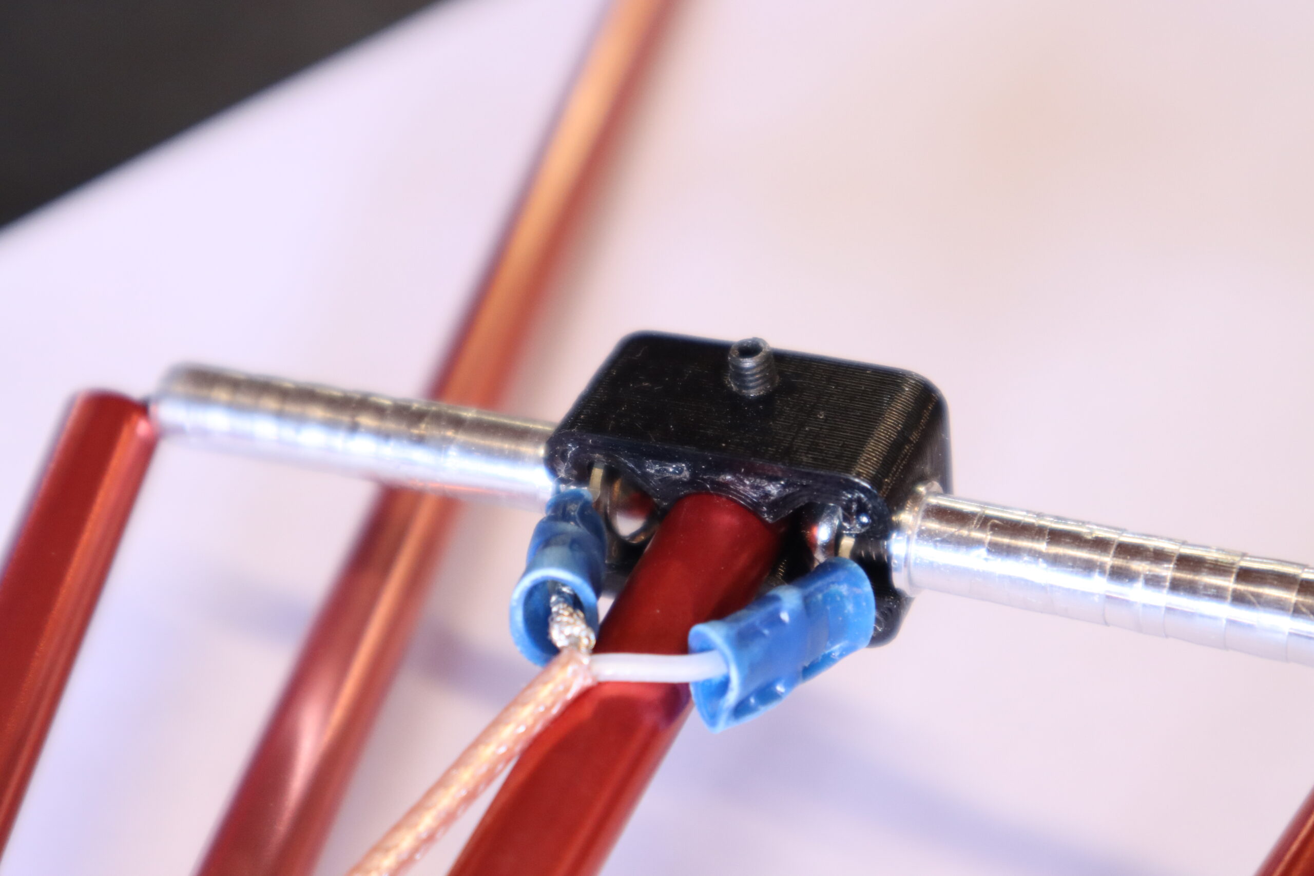
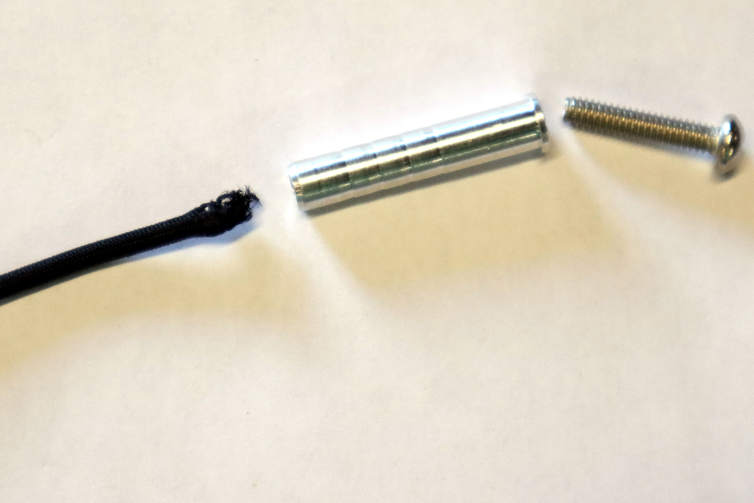
6. Attach Inserts & Screws for the
Attach the shock cord, threaded insert, and screw. Secure shock cord to screw and insert by capturing some of the shock cord outer sheath material in the threads. Leave a gap big enough to slip the assembly into the bracket.

Start with the bracket for the rear (longer) elements. As you secure the threaded inserts and screws to the bracket, use a short piece of wire pinched under the screws to provide an electrical connection between the two sides of the rear elements. Check for continuity with a multi-meter if you have one. These two elements must be electrically connected for the antenna to work.
For the second bracket, include the ring terminals on the ends of the coax on screw, secured under the head of the screw as shown. These two (driven) elements must be electrically isolated from each other for the antenna to work.
Alternatively, epoxy shock cord into the insert after attached to bracket. Secure the screws and inserts as best you can, using pliers to grip the insert while tightening the screw with a screwdriver at an angle (it’s a little tricky).
7. Attach Elements
Tape or tie a piece of string to the end of a shock cord section and use it to pull the shock cord through one of the arrow shaft elements. Be sure to install the shorter elements to the bracket with the coax attached. Wrap the taut shock cord around a finger to prevent it from slipping back through, and feed the end through one more threaded insert, then tie an overhand knot to secure it. Repeat for each element. 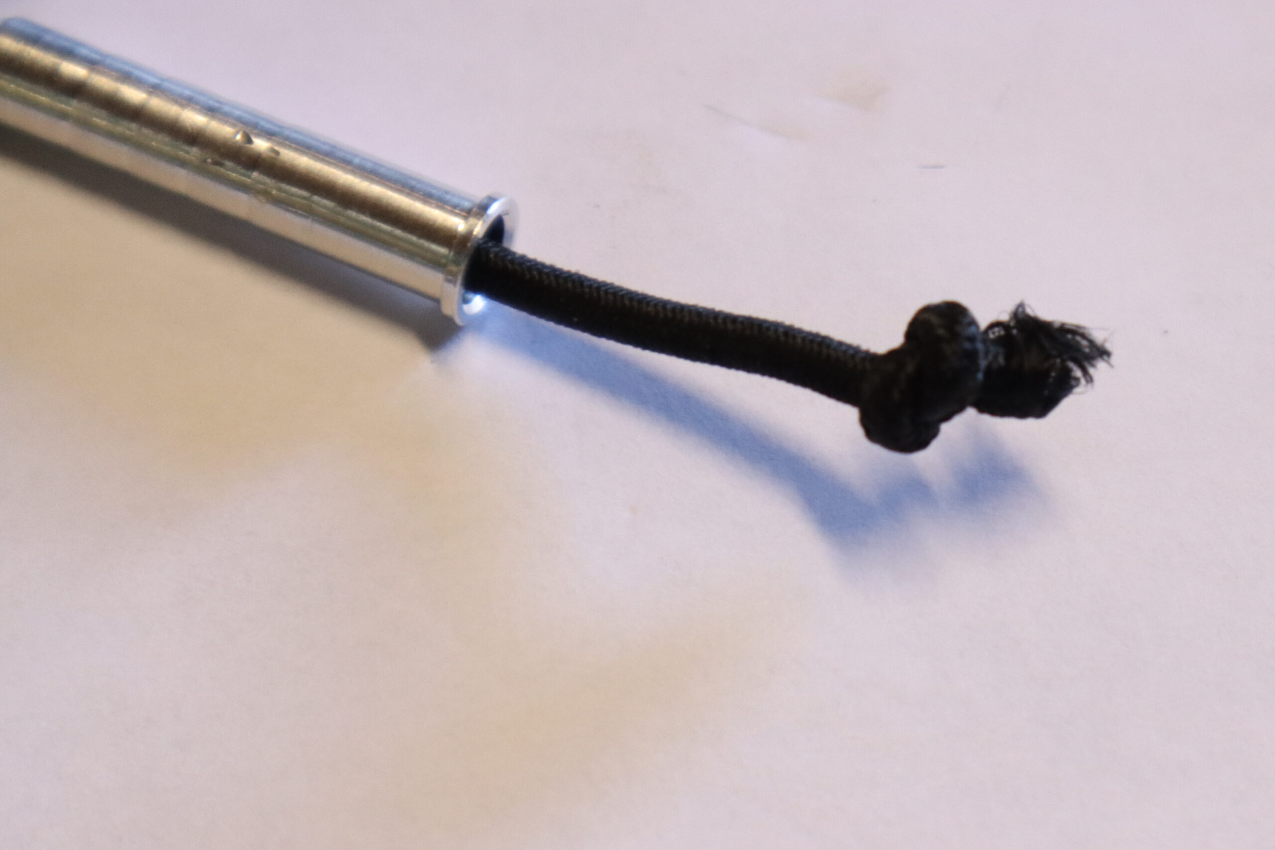

8. Attach the Brackets to the Boom
Slip the brackets into place. Secure them with M3 set screws in the positions shown in the dimensions. Alternatively, drill the holes slightly larger and use 6-32 x 1/4″ screws or epoxy in place if you don’t have spare screws.
9. Attach the Grip
Cut the foam grip and glue onto the boom as a handle.
Optional: use a velcro strap or two to secure the elements when folded.
10. Check the Tuning
Attach an antenna analyzer or NanoVNA and confirm at least a 2:1 SWR match or better.
Have fun and get on the air!
73, Adam – K6ARK